
Checking the gap
- Make
- Fiat
- Model
- Bravo /Brava (182) Factory Service Manual
- Year
- 1995–2001
- Section
- Fuel system (98 range, 1998 20v) › Checking the gap
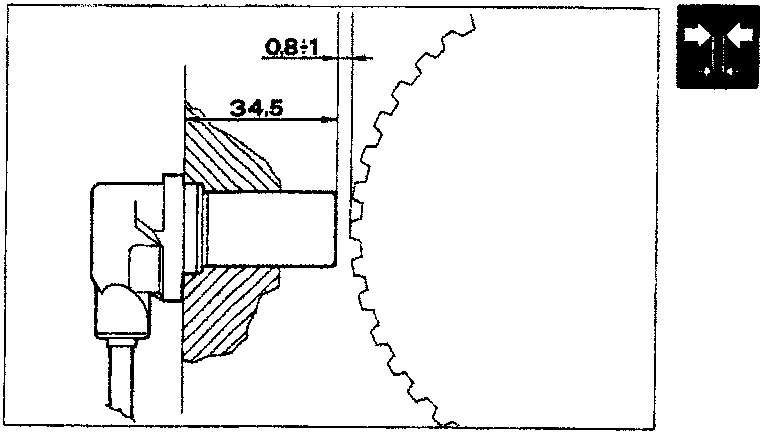
Checking the gap
The rpm and TDC sensor is fixed directly to the cylinder block/crankcase and therefore the gap and the angular position do not need adjusting. If a fault is suspected, the gap can be checked as follows:
- remove the rpm and TDC sensor;
- check that the distance between the surface of the sensor and the flywheel tooth corresponds to the total length of the sensor probe (34.5mm) with the gap (0.8 - 1.5 mm).
When measuring the distance, it is vital to be at right angles to the flywheel and corresponding to a tooth and not a gap.
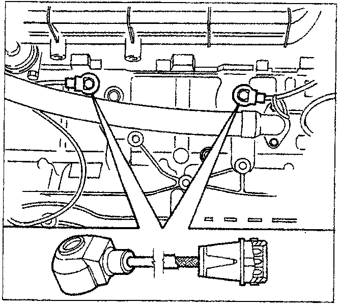
DETONATION SENSORS (0.261.231.131)
The detonation sensors are located in the monobloc under the inlet manifolds and between cylinders 1-2 and 4-5, respectively.
These sensors have a bush to prevent inappropriate torque tightening.
If they are replaced, do not place washers or shims between the cylinder block-/crankcase and sensor contact surfaces.
When the engine is knocking (detonation), vibrations of a certain frequency are produced in the cylinder block/crankcase. This phenomenon produces a mechanical ripercussion on a piezoelectric crystal which sends a signal to the control unit which, on the basis of this signal, reduces the ignition advance (by 3° up to a maximum of 9.7°) until the phenomenon disappears. Later, the advance is gradually restored to the basic value.
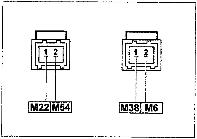
Wiring connector
The sensors are connected to the electronic control unit (Pins M22/M54 and M38/M6) by twisted cables covered in an anti-interference outer casing.
The numbers indicate the corresponding control unit pins.
Parts & tools for this job For 1995 Fiat Bravo
- PARTFuel filterSearch: Fiat Bravo 1995 fuel filter
- TOOLFuel pressure test kitSearch: fuel pressure test kit
- TOOLFuel line disconnect toolSearch: fuel line disconnect tool
Links open Amazon search results in a new tab. As an Amazon Associate I earn from qualifying purchases.