
Checking the resistance
- Make
- Fiat
- Model
- Bravo /Brava (182) Factory Service Manual
- Year
- 1995–2001
- Section
- Fuel system (98 range, 1998 20v) › Checking the resistance
The sensor can be rapidly put out of action by even small amounts of lead in the fuel.
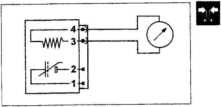
Checking the resistance
The resistance of the heater and the sensor can be measured by disconnecting the connector and connecting an ohmmeter as shown in the diagram.
Resistance = 500-1000 ohm at 20°C
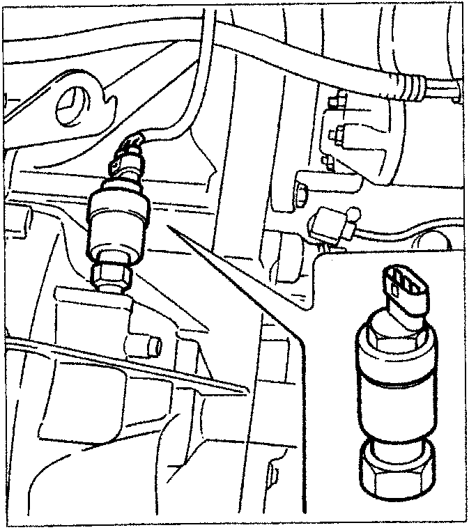
SPEEDOMETER SENSOR
The speedometer sensor (vehicle speed sensor) is positioned at the differential output, by the left driveshaft coupling and transmits information concerning the vehicle speed to the control unit: the signal is also used for the operation of the speedometer.
The sensor is the Hall effect type (see paragraph on "engine timing sensor") and is calibrated so that each impulse corresponds to a distance of one metre; it is possible to know the speed of the vehicle from the frequency of the impulses.
The control unit uses this information for improving the management of the engine idle adjustment actuator and for the CUT-OFF strategy.
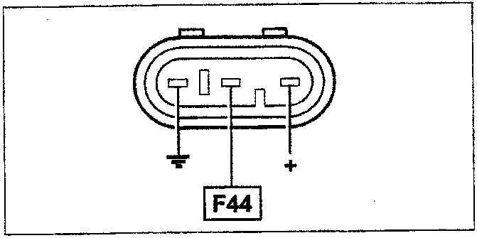
Wiring connector
The numbers indicate the corresponding control unit pins
Parts & tools for this job For 1995 Fiat Bravo
- PARTFuel filterSearch: Fiat Bravo 1995 fuel filter
- TOOLFuel pressure test kitSearch: fuel pressure test kit
- TOOLFuel line disconnect toolSearch: fuel line disconnect tool
Links open Amazon search results in a new tab. As an Amazon Associate I earn from qualifying purchases.