
Coolant temperature sensor
- Make
- Fiat
- Model
- Bravo /Brava (182) Factory Service Manual
- Year
- 1995–2001
- Section
- Fuel system (98 range, 1998 20v) › Coolant temperature sensor
COOLANT TEMPERATURE SENSOR
(Jaeger 402.183.01)
(Elth 2690350)
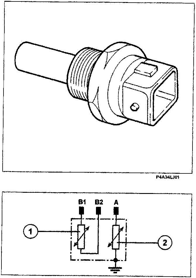
The sensor is fitted on the themostat casing; it is made up of a brass casing which acts as protection against the actual resistive elements made up of two NTC thermistors (Negative Temperature Coefficient, where the electrical resistance of the sensor decreases as the temperature increases). The two NTCs are distinct and provide temperature information to the specific gauge in the Instrument panel and to the injection/ignition control unit. The reference voltage for the NTC element for the injection system is 5 Volt; since the control unit inlet circuit is designed as a voltage divider, this voltage is shared between a resistance in the control unit and the sensor NTC resistance. As a result, the control unit is capable of evaluating the changes in voltage and obtaining temperature information in this way.
- NTC for injection system
- NTC for gauge in Instrument panel
Recovery
The last value detected is taken as valid or a fixed values of 80 °C if the temperature of the intake air is above a given level. The self-adjustment of the mixture strength is inhibited. The radiator fan is activated. The self-adjustment of the idle is inhibited.
Checking the resistance
The table at the side contains the resistance values which the NTC elements can assume according to the temperature. These values can be measured by by disconnecting the connector and connecting an ohmmeter to sensor pins.
Removing-refitting
Disconnect the electrical connection and remove the sensor
Tightening torque 2.2 da Nm.
Wiring connector
The numbers indicate the respective control unit pins
| Ω | °C | Ω | |
|---|---|---|---|
| -20 | 15970 | 40 | 1150 |
| -10 | 9620 | 50 | 807 |
| 0 | 5975 | 60 | 576 |
| 10 | 3816 | 70 | 418 |
| 20 | 2500 | 80 | 309 |
| 25 | 2044 | 90 | 231 |
| 30 | 1679 | 100 | 176 |
| °C | Ω |
|---|---|
| 60 | 512÷602 |
| 90 | 184÷208 |
| 120 | 76÷88 |
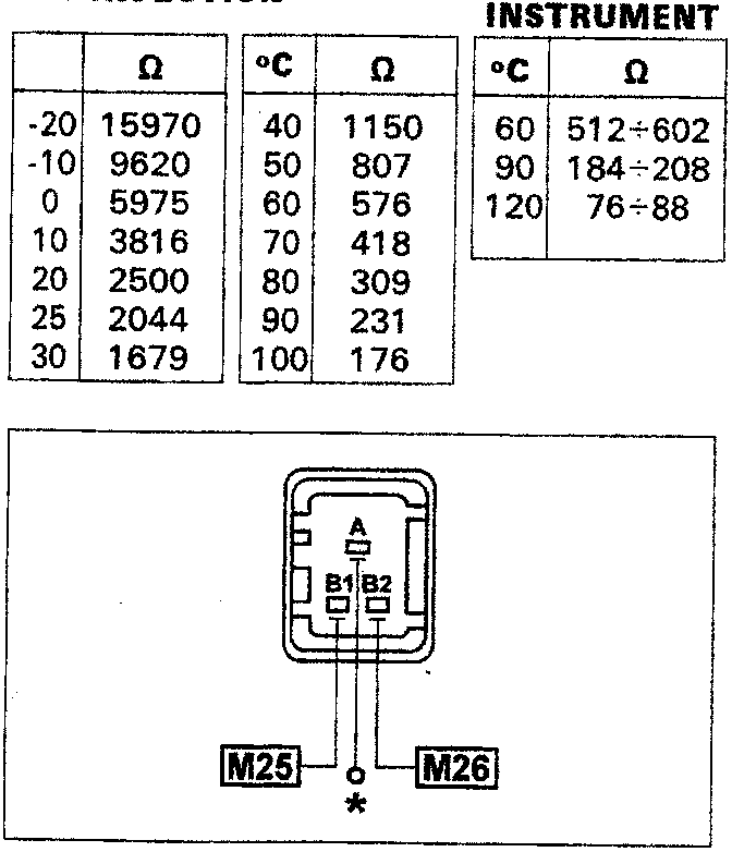
* Connection to the coolant temperature gauge in the Instrument panel
Parts & tools for this job For 1995 Fiat Bravo
- TOOLOBD2 scannerSearch: OBD2 scanner
- TOOLDigital multimeterSearch: automotive digital multimeter
- TOOLBack-probe test leadsSearch: back probe test leads
Links open Amazon search results in a new tab. As an Amazon Associate I earn from qualifying purchases.