
Injection/ignition system components
- Make
- Fiat
- Model
- Bravo /Brava (182) Factory Service Manual
- Year
- 1995–2001
- Section
- Fuel system (98 range, 1998 20v) › Injection/ignition system components
INJECTION/IGNITION SYSTEM COMPONENTS
The injection/ignition system basically consists of wiring, an electronic control unit (I.E. control unit) and the following sensors/actuators:
Sensors
- Speedometer sensor
- Rpm and T.D.C. sensor
- Detonation sensors
- Coolant temperature sensor
- Timing sensor
- Butterfly valve position sensor (integrated in the butterfly casing actuator)
- Intake air temperature sensor
- Intake air temperature and flow rate sensor (flow meter)
- Lambda sensor
- Accelerator pedal potentiometer
- Brake pedal switch
- Clutch pedal switch
Actuators
- Butterfly casing actuator
- Phase transformer solenoid valve
- Fuel vapour cut out solenoid valve
- Variable geometry manifold solenoid valve
- Electric fuel pump (including filter and pressure regulator)
- Injectors
- Ignition coils
- Spark plugs
DIAGNOSTIC SOCKET
The exchange of data between the injection/ignition control unit and the diagnostic equipment takes place via a two direction serial line (line K) using the standard Bosch communication protocol.
The transmission is in positive logic and the coding takes place via the NRZ method (Non Return Zero) at a baud rate of 4.8 kbaud (208 µs/bit ±5%)
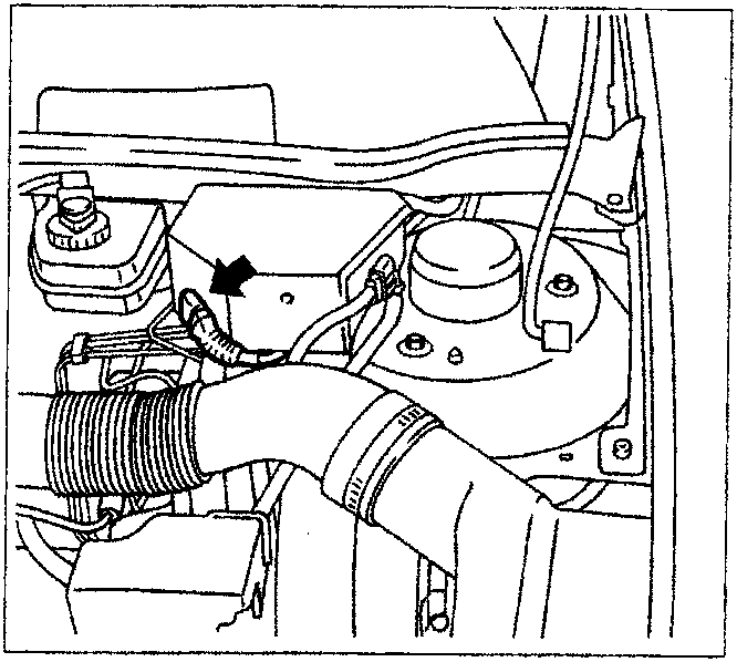
Location of diagnostic socket
The arrow in the diagram shows the location of the diagnostic socket.
INJECTION/IGNITION SYSTEM WIRING
The various system components are connected by two distinct sets of wiring.
The engine side wiring (connector M) connect the components fitted on the engine to the injection control unit; the vehicle side wiring (connector F) connects the other components to the control unit and constitutes the interface with the other vehicle wiring.
The two connectors (M and F) are the same and both have 64 pins, but due to the presence of special keys it is not possible to mix up the control unit connector wiring.
INJECTION/IGNITION ELECTRONIC CONTROL UNIT
The injection/ignition electronic control unit is located in the engine compartment, fixed to a bracket to the side of the inlet manifold.
The control unit processes the signals coming from the various sensors through the application of software algorhythms and operates the actuators (in particular the injectors and the pressure regulator) in order to ensure the optimum engine operation.
The control unit is the "flash E.P.R.O.M." type which can be reprogrammed from the outside without involving the hardware.
Parts & tools for this job For 1995 Fiat Bravo
- PARTSpark plugsSearch: Fiat Bravo 1995 spark plugs
- TOOLSpark plug socketSearch: spark plug socket
- TOOLSpark plug gap toolSearch: spark plug gap tool
Links open Amazon search results in a new tab. As an Amazon Associate I earn from qualifying purchases.