
Fuel vapour recovery
- Make
- Fiat
- Model
- Bravo /Brava (182) Factory Service Manual
- Year
- 1995–2001
- Section
- Fuel system (98 range, 1998 20v) › Fuel vapour recovery
Fuel vapour recovery
The fuel vapours (pollutant according to regulations) are sent to an active charcoal filter and from these to the engine where they are burnt; this takes place by means of a solenoid valve which is only operated by the control unit when the engine load condition is such as to allow correct combustion without the operation of the engine being "disturbed": in effect, the control unit compensates for this quantity of incoming petrol by reducing the supply to the injectors.
Control of the detonation
This function is designed to detect the presence of the phenomenon of detonation (engine knock), by processing the signal coming from the appropriate sensors. The control unit continuously compares the signals coming from the sensors with a threshold value which is, in turn, constantly updated to take into account background noise and the ageing of the engine.
The control unit is therefore capable of detecting the presence of detonation (or the onset of detonation) and reduces the ignition advance (by 3° up to a maximum of about 9°), until the phenomenon disappears. Later on, the advance is gradually restored to the basic value.
In acceleration conditions, a higher threshhold is used, to take into account the increased engine noise under these circumstances. The detonation control strategy is also equipped with a self-adjustment function which memorizes the reductions in the advance which are continuously repeated to adpat the map to the different conditions in which the engine finds itself.
Control of the phase transformer
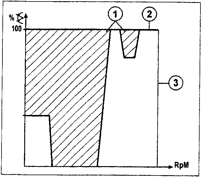
- Transformer in ON position
- Accelerator pedal fully depressed
- Maximum speed limit
The control unit controls the solenoid valve for the phase transformer hydraulic actuator (fitted on the camshaft, inlet side) by means of a relay.
The transformer has two operating positions:
A. OFF position (power, reduced engine loads and idling), corresponding to the normal camshaft value;
B. ON position (torque), corresponding to an 18° crankshaft advance for the camshaft.
The transformer, normally in the OFF position, is switchedto the ON position according to the engine load and rotation speed, as illustrated in the diagram.
In any case, the ON position is only enabled for coolant temperatures above 40°C.
Obviously the control of the phase transformer operates with a hysteresis field, in other words the level at which the solenoid valve is activated is always higher than the level at which is it deactivated; this is designed to avoid balance conditions and too rapid a succession from one timing diagram to another with obvious operating problems.
Check on the inlet manifold
The control unit controls the geometry of the inlet manifolds to optimize the quantity of air drawn in by the engine.
The control unit selects short ducts for speeds above 4500 RPM and high engine loads.
In other engine operating conditions, the control unit selects a configuration with long ducts.
Parts & tools for this job For 1995 Fiat Bravo
- PARTFuel filterSearch: Fiat Bravo 1995 fuel filter
- TOOLFuel pressure test kitSearch: fuel pressure test kit
- TOOLFuel line disconnect toolSearch: fuel line disconnect tool
Links open Amazon search results in a new tab. As an Amazon Associate I earn from qualifying purchases.