
Checking the resistance
- Make
- Fiat
- Model
- Bravo /Brava (182) Factory Service Manual
- Year
- 1995–2001
- Section
- Fuel system (98 range, 1998 20v) › Checking the resistance
Checking the resistance
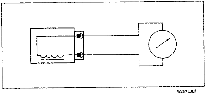
The resistance of the solenoid valve can be measured by disconnecting the connector and connecting an ohmmeter as illustrated in the diagram.
Resistance: 17.5-23.5 ohm at 20 °C
Wiring connector
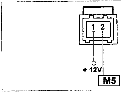
The numbers indicate the corresponding control unit pins
CHECKS - ADJUSTMENTS AND REPAIR OPERATIONS ON THE BOSCH MOTRONIC ME 3.1 INJECTION/IGNITION SYSTEM IN ADDITION TO THE FAULT DIAGNOSIS
WHEN WORKING ON A VEHICLE EQUIPPED WITH A MOTRONIC INJECTION/IGNITION SYSTEM, OBSERVE THE FOLLOWING PRECAUTIONS:
- do not start up the engine with the terminals for the electrical connections not properly connected or slack at the battery poles;
- do not use a rapid battery charger to start the engine;
- never disconnect the battery from the on board system with the engine running;
- when recharging the battery, disconnect it first from the system;
- if the vehicle goes into a drying oven after painting, at temperatures in excess of 80 °C, then the injection/ignition electronic control unit must be removed first;
- never connect or disconnect the electronic control unit multiple connector with the ignition switch in the ON position;
- always disconnect the negative battery lead before carrying out electrical welding on the vehicle.
It should be remembered that this system has a memory which is always supplied (stand-by memory) which contains all the self-adjustment figures. If the battery is disconnected then this information is lost and can only be acquired again after a certain length of time so this operation should be carried out as infrequently as possible.
If the engine control unit or the motorized butterfly casing is being replaced, the self-learning procedure must be carried out for the return spring inside the butterfly casing and maximum/minimum motorized butterfly valve angular positions.
Parts & tools for this job For 1995 Fiat Bravo
- PARTFuel filterSearch: Fiat Bravo 1995 fuel filter
- TOOLFuel pressure test kitSearch: fuel pressure test kit
- TOOLFuel line disconnect toolSearch: fuel line disconnect tool
Links open Amazon search results in a new tab. As an Amazon Associate I earn from qualifying purchases.