
Engine Timing Sensor
- Make
- Fiat
- Model
- Bravo /Brava (182) Factory Service Manual
- Year
- 1995–2001
- Section
- Fuel system (99 range, 1747 16v) › Engine Timing Sensor
Engine Timing Sensor
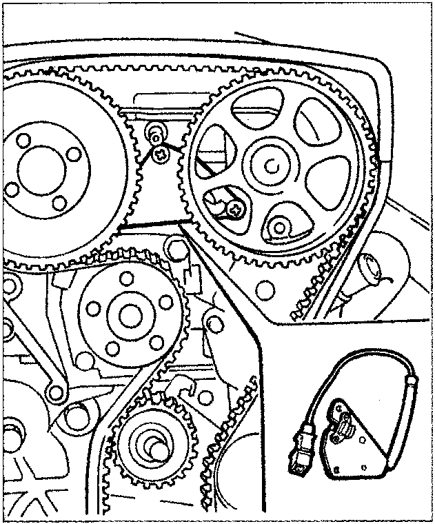
The engine timing signal, together with the engine rpm and TDC signal, allows the control unit to recognize the order of the cylinders to implement phased injection.
This signal is produced by a Hall effect sensor, fitted by the exhaust camshaft drive pulley.
NOTE The angular position of the sensor cannot be adjusted in any way.
Operating principle
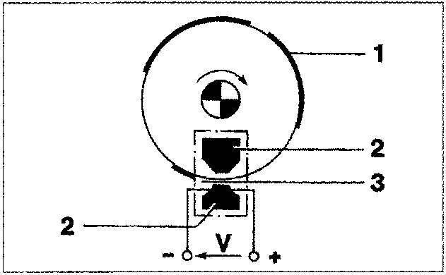
- Deflector
- Magnetic material
- Gap
A semi-condulator layer, through which a current passes, immersed in a magnetic field (lines of force perpendicular to the direction of the current), produces a difference in power, known as Hall voltage.
If the intensity of the current remains constant, the voltage produced only depends on the intensity of the magnetic field. The intensity of the field can simply be altered periodically to produce a modulated electrical signal.
In practice, to achieve this change, the sensor is passed through a metal ring (in one piece with the inner part of the timing pulley) which has a series of openings: as it moves, when the ring covers the sensor, it stops the magnetic field and the signal remains low, whilst when there is an opening, the field is enclosed and the signal becomes high
The alternating of the signals depends therefore on the succession of the openings (see chapter on "signal management").
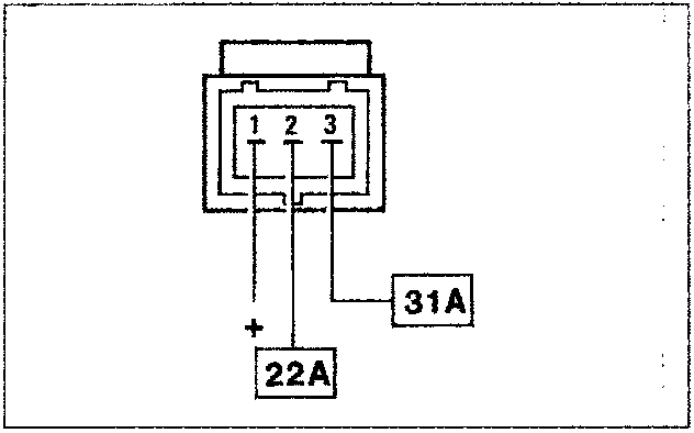
Wiring connector
Parts & tools for this job For 1995 Fiat Bravo
- TOOLOBD2 scannerSearch: OBD2 scanner
- TOOLDigital multimeterSearch: automotive digital multimeter
- TOOLBack-probe test leadsSearch: back probe test leads
Links open Amazon search results in a new tab. As an Amazon Associate I earn from qualifying purchases.