
Wiring connector
- Make
- Fiat
- Model
- Bravo /Brava (182) Factory Service Manual
- Year
- 1995–2001
- Section
- Fuel system (99 range, 1747 16v) › Wiring connector
The injector has the task of supplying the quantity of fuel needed for the operation of the engine: the fuel is njected nto the intake manifold, immediately upstream of the inlet valves.
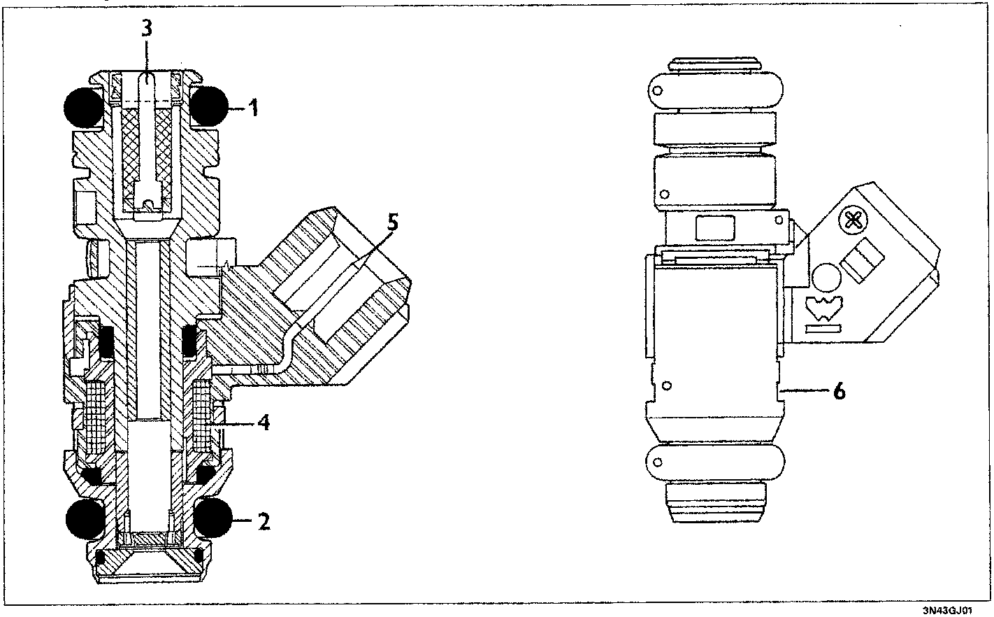
The injector is the twin jet, top-feed type, with the supply (3) of fuel at the top where the electrical winding (4) connected to the connector terminals (5) is also housed.
When the current passes through the winding, the magnetic field which is produced attracts the shutter causing the opening of the injector and the flow of fuel.
Two seals guarantee the seal on the fuel manifold side (1) and the intake manifold side (2). A reference (6) determines the angular position of the injector in relation to the inlet duct to ensure the correct direction of the jets in relation to the inlet valves.
Wiring connector
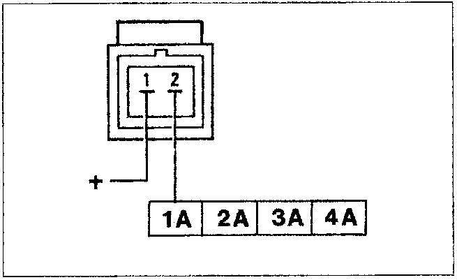
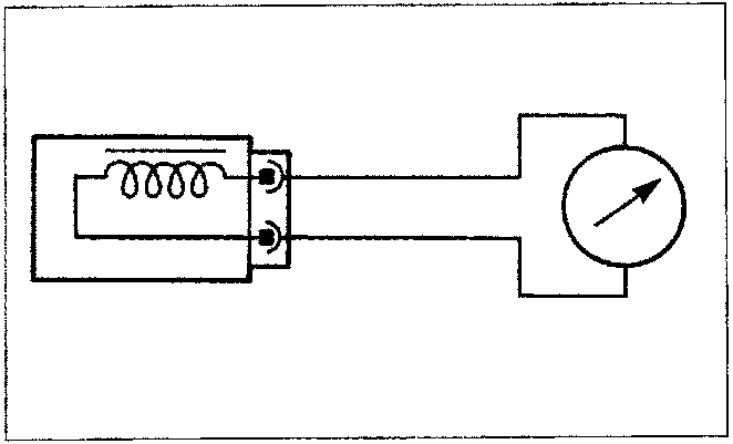
The injector resistance can be measured by disconnecting the connector and connecting an ohmmeter as illustrated in the diagram.
Resistance value: 14.5 ± 5% ohm
Parts & tools for this job For 1995 Fiat Bravo
- TOOLDigital multimeterSearch: automotive digital multimeter
- PARTAssorted fuse kitSearch: car fuse assortment kit
- TOOLWire crimper and connector kitSearch: wire crimper connector kit
Links open Amazon search results in a new tab. As an Amazon Associate I earn from qualifying purchases.