
Wiring connector
- Make
- Fiat
- Model
- Bravo /Brava (182) Factory Service Manual
- Year
- 1995–2001
- Section
- Fuel system (99 range, 1747 16v) › Wiring connector
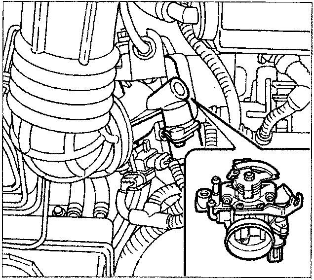
Wiring connector
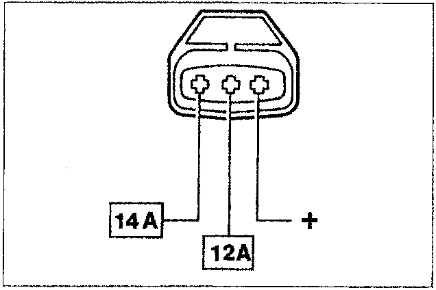
AIR FLOW METER
The air flow meter is the hot film type, incorporated in the butterfly casing.
The top part has a duct, parallel to the main flow, which contains the heated filament.
Part of the flow of intake air is introduced into the duct and, after passing through it, comes out the opposite side, returning to the main flow.
As a result, only part of the mass of air which passes through the flow meter is measured: this quantity is, however, proportional to the overall mass which passes through the flow meter.
The flow meter output electrical voltage is therefore representative of the total flow rate.
This type of flow meter has two advantages compared with the full flow type:
- considerable insensitivity to the pulsation of the columns of air, especially present at low speeds and heavy loads;
- less fouling of the filament, thanks to the reduced mass of air which comes into contact with it; as a result, the control unit has no wire cleaning strategy (burn-in).
Parts & tools for this job For 1995 Fiat Bravo
- TOOLDigital multimeterSearch: automotive digital multimeter
- PARTAssorted fuse kitSearch: car fuse assortment kit
- TOOLWire crimper and connector kitSearch: wire crimper connector kit
Links open Amazon search results in a new tab. As an Amazon Associate I earn from qualifying purchases.