
Lambda sensor
- Make
- Fiat
- Model
- Bravo /Brava (182) Factory Service Manual
- Year
- 1995–2001
- Section
- Fuel system (99 range, 1747 16v) › Lambda sensor
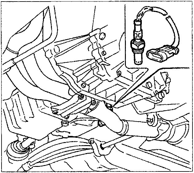
LAMBDA SENSOR
The Lambda sensor measures the oxygen content in the exhaust gases: it is fitted on the exhaust pipe, upstream of the catalytic silencer. The sensor output signal is sent to the control unit for a feed-back correction of the mixture strength.
When the sensor supplies a low signal (voltage below 200 mV) the control unit recognizes a weak mixture and increases the injection time; later on, when the sensor signal is high (voltage above 800 mV), the control unit recognizes a rich mixture and decreases the injection time.
This sequence is repeated at a frequency in the order of tens of Hertz so that the engine operates with a mixture strength constantly fluctuating around the stoichiometric ratio.
At temperatures below 300°C the ceramic material is not activated, therefore the sensor does not send reliable signals: to ensure rapid heating during starting and maintain the temperature whilst idling, the sensor is equipped with a heater with an electrical resistance which is always on.
The sensor can be rapidly put out of action by the presence of even slight amounts of lead in the petrol.
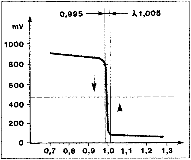
λ = 1 Ideal mixture (stoichiometric)
λ > 1 Lean mixture
Excess air, the CO values tend to be low
λ < 1 Rich mixture
Lack of air; the CO values tend to be high
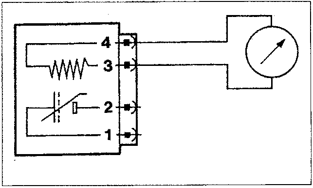
The sensor heater resistance can be measured by disconnecting the connector and connecting an ohmmeter as illustrated in the diagram.
Wiring connector
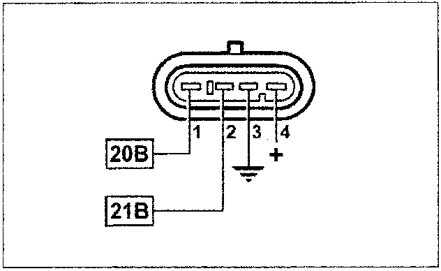
Resistance: 4.5 ± 0.5 ohm at 20°C
Parts & tools for this job For 1995 Fiat Bravo
- PARTOxygen sensorSearch: Fiat Bravo 1995 oxygen sensor
- TOOLOxygen sensor socketSearch: oxygen sensor socket
- TOOLOBD2 scannerSearch: OBD2 scanner
Links open Amazon search results in a new tab. As an Amazon Associate I earn from qualifying purchases.