
Intake circuit
- Make
- Fiat
- Model
- Bravo /Brava (182) Factory Service Manual
- Year
- 1995–2001
- Section
- Fuel system (99 range, 1747 16v) › Intake circuit
INTAKE CIRCUIT
The intake circuit consists of the following components:
- air filter and hoses;
- acoustic resonators fitted in parallel to the intake hose (two upstream and one downstream of the filter);
- intake manifold on which the fuel manifold, complete with injectors, the engine management control unit and the charcoal filter solenoid valve are fitted
- butterfly casing, incorporated with the air flow meter, on which the butterfly position sensor, the PCV valve for the oil vapour recirculation circuit and the engine idle adjustment actuator are fitted.
BUTTERFLY CASING
The butterfly casing has the task of metering the quantity of air drawn in by the engine (and consequently the power developed) according to the driver's request via the accelerator and it is incorporated with the air flow meter.
The butterfly casing is secured to the intake manifold by four bolts: the butterfly is opened by means of linkage where small butterfly opening angles correspond to the pedal being slightly pressed and large angles correspond to it being greatly depressed.
With the pedal completely released (engine decelerating or idling) the necessary additional air is supplied by the engine idle adjustment actuator: under these circumstances, the butterfly opening lever is in the end of travel position against an anti-tamper screw which prevents the butterfly from getting stuck in a closed position.
To prevent the formation of ice near the butterfly and the opening connected to the PCV valve, the butterfly casing is heated by a small amount of water coming from the engine thermostat circulating in a chamber inside the actual casing.
The PCV valve for the oil vapour recirculation system and the butterfly position sensor are also fitted on the butterfly casing.
The anti-tamper screw is adjusted during the fluxing operation in the factor and should never be tampered with.
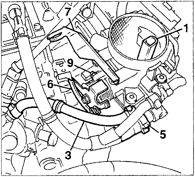
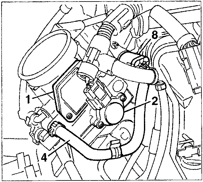
- Air flow meter
- Butterfly position sensor
- Engine coolant inlet
- Engine coolant outlet
- PCV valve
Parts & tools for this job For 1995 Fiat Bravo
- TOOLDigital multimeterSearch: automotive digital multimeter
- PARTAssorted fuse kitSearch: car fuse assortment kit
- TOOLWire crimper and connector kitSearch: wire crimper connector kit
Links open Amazon search results in a new tab. As an Amazon Associate I earn from qualifying purchases.