
Paao4bxo03 (page 2 of 6)
- Make
- Fiat
- Model
- Bravo /Brava (182) Factory Service Manual
- Year
- 1995–2001
- Section
- Removing-refitting (1747 16v)
10 EnginePaao4bxo03 · page 2 of 6
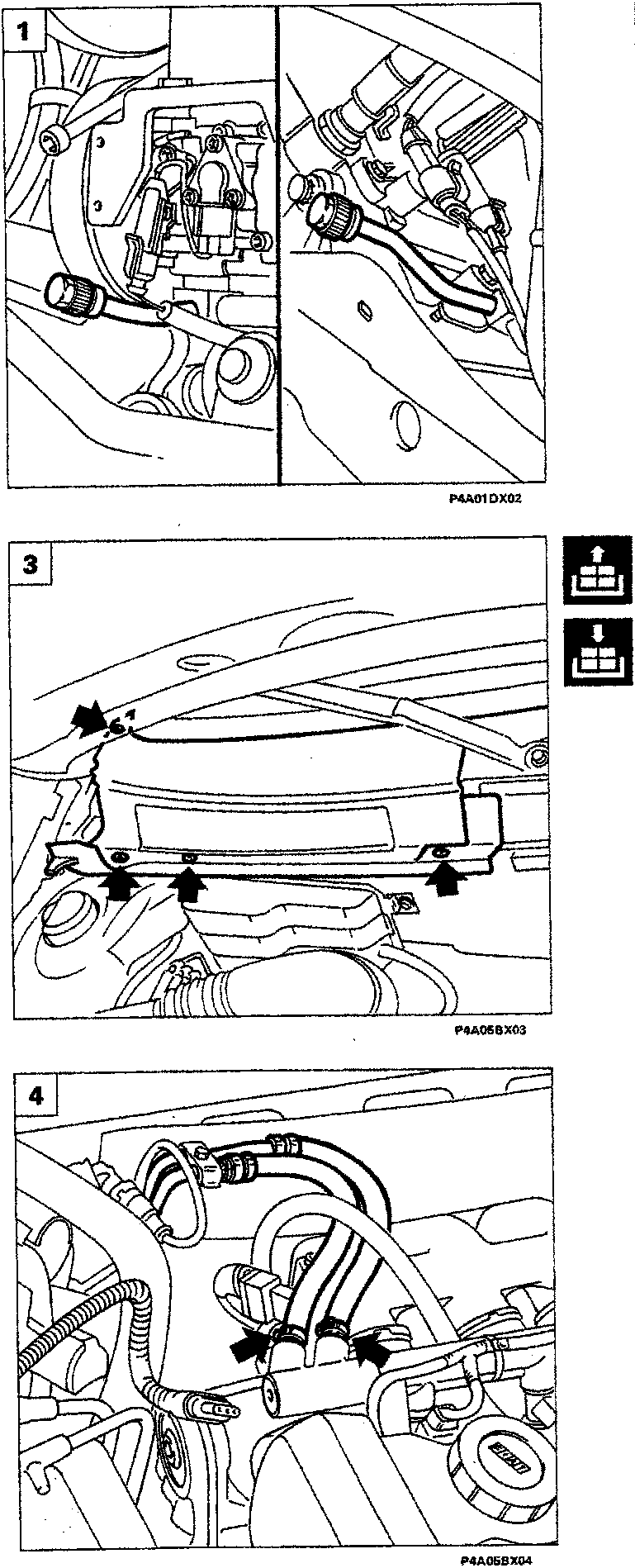
- Drain the air conditioning system connecting the special equipment to the needle valves shown in the diagram. Proceed as described in Section 50 - Auxiliary units in this manual.
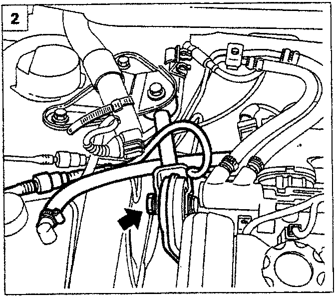
- Disconnect the coolant pipe and the anti-evaporation pipe shown, then remove the reaction rod.
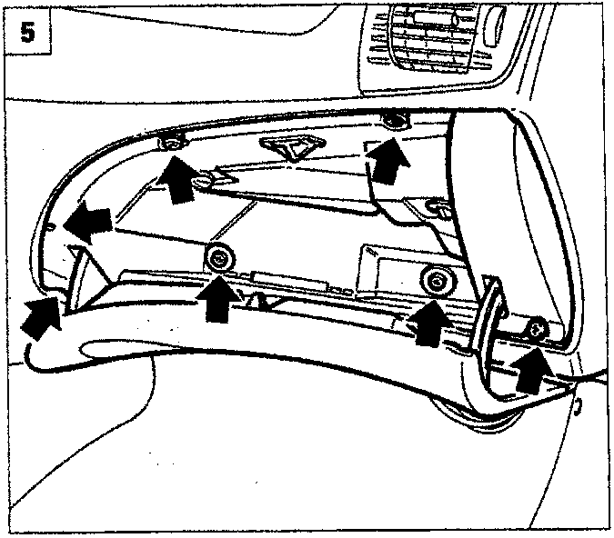
- Remove the plastic shield shown in the diagram, acting on the fixing bolts; in order to be able to remove it it is necessary to remove the windscreen wiper blade.
- Disconnect the fuel supply and return pipes from the manifold at the points shown:
- Working from inside the vehicle, remove the glove compartment.
Parts & tools for this job For 1995 Fiat Bravo
- PARTEngine gasket setSearch: Fiat Bravo 1995 engine gasket set
- TOOLTorque wrenchSearch: 3/8 inch torque wrench
- TOOLFeeler gauge setSearch: feeler gauge set
Links open Amazon search results in a new tab. As an Amazon Associate I earn from qualifying purchases.