
Paao4bxo03 (page 5 of 6)
- Make
- Fiat
- Model
- Bravo /Brava (182) Factory Service Manual
- Year
- 1995–2001
- Section
- Removing-refitting (1747 16v)
10 EnginePaao4bxo03 · page 5 of 6
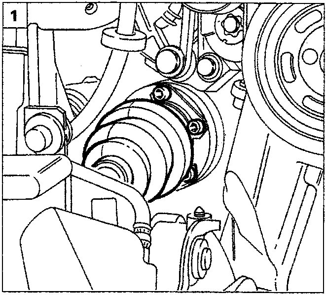
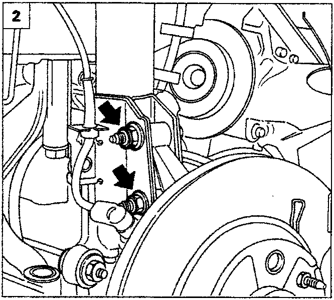
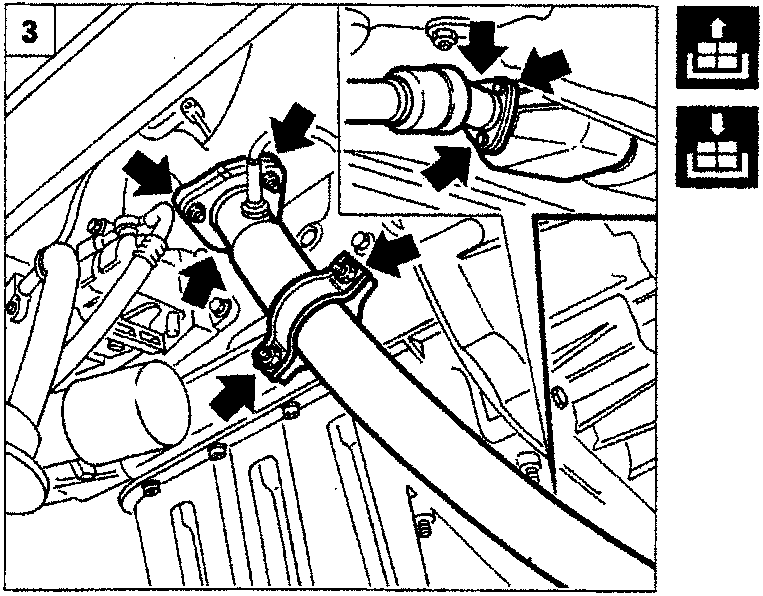
- Undo the bolts fixing the right drive shaft flange.
- Remove the upper bolt fixing the shock absorber to the steering knuckle and loosen the lower one to allow the removal of the drive shaft.
- Remove the first section of the exhaust pipe acting on the fixings shown in the diagram.
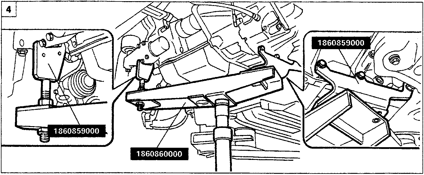
- Position tool 1860860000 supporting the power unit on the hydraulic jack and fix it to the power unit using tools 1860859000 at the points shown in the diagram.
Parts & tools for this job For 1995 Fiat Bravo
- PARTEngine gasket setSearch: Fiat Bravo 1995 engine gasket set
- TOOLTorque wrenchSearch: 3/8 inch torque wrench
- TOOLFeeler gauge setSearch: feeler gauge set
Links open Amazon search results in a new tab. As an Amazon Associate I earn from qualifying purchases.