
Compressor (page 2 of 3)
- Make
- Fiat
- Model
- Bravo /Brava (182) Factory Service Manual
- Year
- 1995–2001
- Section
- Compressor
50 Auxiliary unitsCompressor · page 2 of 3
NOTE The compressor shaft and inner part of front mount, containing both gasket seats, must be perfectly clean.
Before fitting the new gaskets, ensure that these are not scratched or damaged and that surfaces are not contaminated with lint which could affect the seal.
Ensure the flat face of the retaining ring is turned towards the gasket.
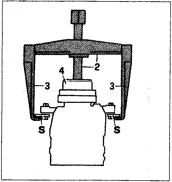
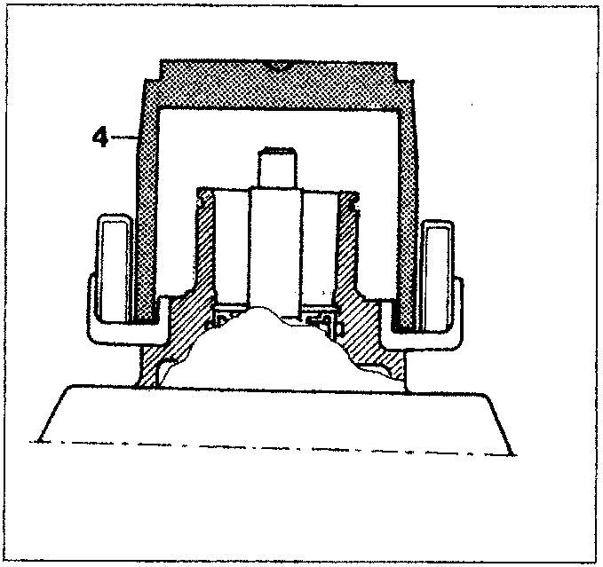
- Use a file to remove the notches on the outer part of the front compressor mount, then fit new electromagnetic coupling winding using axle 1840005004 (2), brackets 1840005303 (3), clamp 1840005400 and part 1877511000 (4). Take note of contact position marked previously. The above brackets must be fastened to support (S) to which compressor is secured (as shown in top left-hand figure).
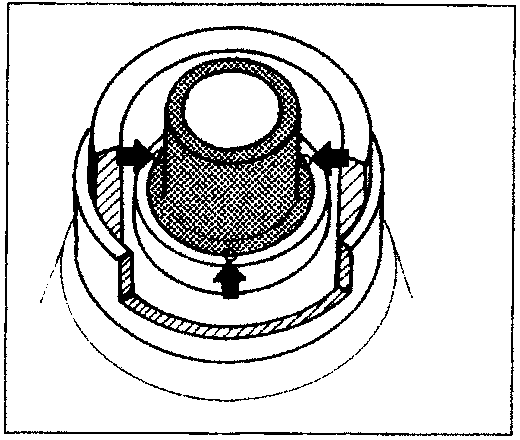
Once the winding has been positioned in its seat, secure by using a 3 mm drift to make three notches on the front compressor mount (shaded) at 120° apart (see arrows).
Notch size should be about half that of drift tip and depth should be no greater than 0.35 mm.
Parts & tools for this job For 1995 Fiat Bravo
- TOOLTorque wrenchSearch: 3/8 inch torque wrench
- TOOLSocket setSearch: socket set metric
- BOOKHaynes manualSearch: Haynes manual Fiat Bravo
Links open Amazon search results in a new tab. As an Amazon Associate I earn from qualifying purchases.