
Introduction - exterior lighting
- Make
- Fiat
- Model
- Croma Factory Service Manual
- Year
- 2005–2010
- Section
- Exterior lighting › Introduction - exterior lighting
INTRODUCTION - EXTERIOR LIGHTING
INTRODUCTION
The vehicle exterior lighting system has been designed and produced with two objectives in mind:
- guaranteeing maximum efficiency with regard to the international regulations that define the lighting technology specifications for the various components;
- being integrated with the design of the vehicle so that the various components enhance the image.
The side light, dipped headlamp, main beam hedlamp and direction indicator are in a single front unit, managed separately.
The fog light, on the other hand, has its own lamp.
The vehicle components and their location are illustrated below.
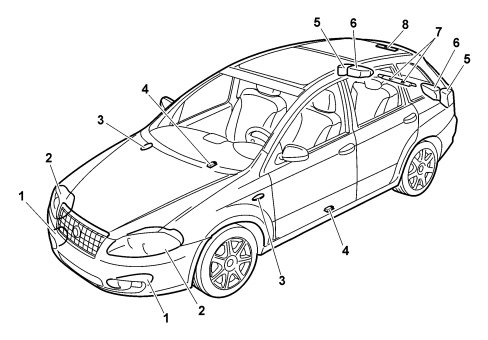
1 - Fog lights
2 - Front light clusters
3 - Side direction indicators
4 - Puddle lights
5 - Rear light clusters on bodyshell (fixed parts)
6 - Rear light clusters on tailgate (moving parts)
7 - Number plate lights
8 - Third brake light
FRONT LIGHT CLUSTER
The light cluster is composed as follows:
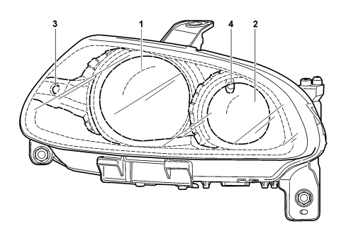
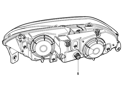
1 - Dipped headlamp
2 - Main beam headlamp
3 - Direction indicator
4 - Side light
5 - Connection for all light functions + headlamp alignment motor
The light cluster is constructed using fixed transparent lens technology for all the functions (side light, dipped headlamp, main beam headlamp).
The lamp casing houses the automatic type electric correcter with the control in the instrument panel. The reflective parabolas are made from a metallic thermo-setting material and are covered in a clear paint with a protective function.
The lamp contains the following bulbs:
- H7 halogen long life bulb for dipped headlights function 12V-55W
- H1 halogen bulb for main beam headlights function 12V-55W
- W5W blue vision long life bulb for side lights function 12V-5W
- PY21W bulb for direction indicators function 12V- 21W
A dimmer in front of the dipped headlamp bulb prevents the direct rays from escaping.
The (glass function) lens cover is made from colourless polycarbonate, with a scratch-resistant treatment; there are two openings at the rear with covers for access to the bulb compartments, the first for the dipped headlamp and direction indicators functions; the second for the main beam and side lights functions.
Connector pin out
The pin out for the connector is illustrated in the diagram below.
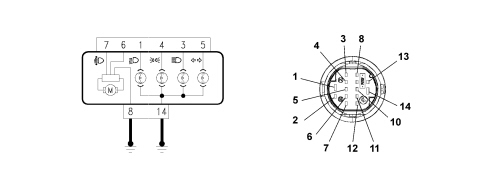
| Pin | Function |
|---|---|
| 1 | Dipped headlight |
| 3 | Main beam headlight |
| 4 | Side light |
| 5 | Direction indicator |
| 6 | Headlight alignment motor (+) |
| 7 | Headlight alignment motor (signal) |
| 8 | Headlight alignment motor (-) |
| 14 | Bulb earth |
FOG LIGHTS
The fog light basically consists of a single block located in the special housings in the front bumper; it comprises a solid body and a cover with a connector through which it is possible to gain access if the bulb needs replacing. A special adjustment screw makes it possible to adjust the light beam manually.
The lamp contains the following type of bulb:
- H 1.55 W bulb
REAR LIGHT CLUSTER
The rear light cluster consists of two parts: one fixed part located directly on the bodywork and one moving part located on the tailgate. The light cluster carries out the following functions:
- Side light
- Brake light
- Reversing light
- Direction indicator
- Brake light
- Rear fog lamp
The fixed part of the rear light cluster contains the following bulbs:
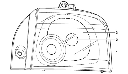
1 - Direction indicator
2 - Brake light
3 - Side light
The bulbs are:
- 5 W bulb for side lights function
- 21W bulb for brake lights function
- 10W bulb for direction indicators function
CONNECTOR PIN OUT
The pin out for the connector is illustrated in the diagram below.

| Pin | Function |
|---|---|
| 1 | Earth |
| 2 | Side light |
| 3 | Brake light |
| 4 | Direction indicator |
The moving part of the rear light cluster on the tailgate contains the following bulbs:
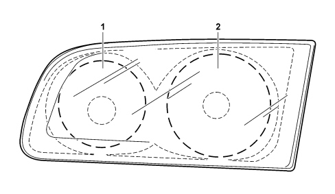
1 - Rear fog lamp
2 - Reversing light
The bulbs are:
- P 21 W bulb for rear fog lamps function
- P 21 W bulb for reversing lights function
CONNECTOR PIN OUT
The pin out for the connector is illustrated in the diagram below.

| Pin | Function |
|---|---|
| 1 | Earth |
| 2 | Rear fog lamp |
| 3 | Reverse gear |
DIRECTION INDICATORS SIDE REPEATER
The side light is illustrated in the diagram.
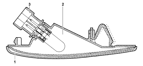
1 - Lens cover
2 - Grey casing
3 - Connector
The bulb is:
- PY 21 WP 5W bulb for side direction indicator function.
To replace the bulb, the lens cover has to be removed manually, releasing the retainers and rotating the bulb holder in an ainti-clockwise direction, extracting it from the lens cover; then keep the bulb
NUMBER PLATE LIGHT
The number plate light function is achieved by means of two lights fitted using a metal clip and a catch projection fastened to the trim. Each light has a bulb on the connector.
The bulbs are:
- C 5 W bulb for rear number plate lights function
To replace the bulb, extract the entire casing by hand releasing it from the clip, release the connector from the housing and keep the bulb.
COURTESY (PUDDLE) LIGHTS
The switching on of the various lamps located in the lower part of the front doors is managed by the signals coming from microswitches which send an earth signal to the Body Computer which notifies the driver''s door and passenger doors nodes, via the CAN, of the door status.
Opening one of the doors causes the lights to come on for a maximum period of 3 minutes. When this timed period expires it will only be possible to reactivate the puddle lights after one of the doors has been reopened once again.
Closing both doors causes the lights to go out immediately.
ADDITIONAL BRAKE LIGHT
The additional side light is illustrated in the diagram.
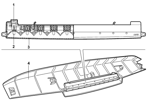
1 - Connector block
2 - Lamp
3 - (Red) lens cover
4 - Mount
The bulbs are:
- N° 10 Bulbs type W 2.3 W - 2.3 W
The function of the additional brake light is achieved by the multibulb lamp with a light beam coming out of the windscreen serigraphy fitted on the top part of the tailgate.
To replace the bulbs, extract the entire casing securing the third brake light by hand; release the connector from the housing, release the fastening tabs and keep the bulbs.
LIGHTS OPERATION
Left control panel
The left control panel is located to the left of the steering wheel and it carries out the following functions: fog lights, rear fog lamps, parking lights, headlamp alignment adjustment and dusk sensor sensitivity settings.
The control panel is illustrated in the diagram.
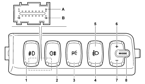
1 - Fog lights on/off button.
2 - Rear fog lamps on/off button.
3 - Park button (parking lights)
4 - Headlamp alignment adjuster "-" (lowering of light beam)
5 - Headlamp alignment adjuster "+" (raising of light beam)
6 - MODE "-" button
7 - MODE "+" button
8 - MODE button
On versions with gas discharge headlamps, the headlamp alignment adjustment is automatic therefore the button in the left control panel is replaced by a plug.
Connector A/B pin out (9+9 way)
| Pin | Function |
|---|---|
| 1 | Negative signal from rear fog lamps control |
| 2 | Fog lights control negative signal |
| 8 | Negative signal from MODE/DIM "-" control |
| 10 | Parking lights control negative signal |
| 11 | Earth |
| 12 | Analogue signal from MODE/DIM "+" control |
| 17 | Ideogram light dimmed supply |
| 18 | Analogue signal from headlamp alignment control |
Side lights and number plate light
When the ring nut on the left steering column switch unit lever is turned once, the side lights/no. plate lights circuit is enabled.
The switching on of the side lights is managed by the Body Computer: the side lights control function is activated through the enablement signals with the key inserted and turned to the ON position and the specific command from the steering column switch unit.
The activation and/or deactivation information is sent via the CAN and the side lights warning light in the instrument panel is switched on together with the activation of the serigraphy lighting.
The operation of the parking lights function, on the other hand, is different; in this case the key should be extracted (STOP) or turned to the OFF position and the PARK button in the panel on the left side of the steering wheel pressed enabling he parking lights function. The engagement of the above control is signalled by a roger beep.
By turning the left steering column switch unit lever (in the same way as for activating the direction indicator) the activation of the lights on the left side of the vehicle can be selected; with the steering column switch unit lever turned completely towards the right the lights on the right side of the vehicle come on and with the steering column switch unit lever in the centre position the lights on both sides of the vehicle come on.
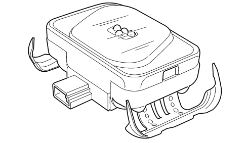
Dusk sensor
The side lights and the dipped headlamps can also be turned on automatically if the AUTO function is set on the steering column switch unit. The dusk sensor, located in the electrochromic mirror, is an infrared device that works on three sensitivity settings duely shownn in the display; the default setting is the second level, but it is possible to alter the sensitivity (from 1 to 3) using the "Mode +" and "Mode -" buttons located in the panel to the left of the steering wheel.
Dusk/rain sensor
Follow me home
The "Follow me home" function allows the dipped headlamps and the side lights to remain on even after the engine has been switched off (key extracted - STOP - or turned to OFF) for a period of 30 seconds or multiples thereof. The lights are activated by operating the light flasher stalk within 2 minutes of switching the engine off: each time the lever is operated, the period for which the lights are on is increased by 30 seconds to a maximum of 210 seconds. The function is excluded if the ignition is turned ON or if the flasher lever is operated for more than two seconds.
Dipped beams
The vehicle is equipped with two dipped beams in the headlamps.
When the ring nut on the left steering column switch unit lever is turned twice, the dipped headlamps circuit is enabled.
The switching on of the dipped headlamps is managed by the Body Computer: the dipped headlamps control function is activated through the enablement signals with the key inserted and turned to the ON position and the specific command from the steering column switch unit.
With the dipped headlamps on, the simultaneous presence of the main beam and fog lights commands disables the dipped headlamps. The subsequent deactivation of one of these two commands, with the dipped headlamps control still on, means that the dipped headlamps will be turned back on again.
Main beams
The vehicle is equipped with two main beams in the headlamps.
There are two different types of operation for the main beams:
- when the dipped beams are on, by pulling the left steering column switch unit lever toward the dashboard (2nd unstable position);
- in flashing mode, irrespective of wheel position, by pulling the left lever towards the steering wheel (1st unstable position);
A special relay - managed by the Body Computer - controls the engagement of the main beam headlamps using the enablement signals with the ignition ON and the specific steering column switch unit command signal.
The activation and/or deactivation information acquired is sent via the CAN to switch the main beam headlamps warning light in the instrument panel on or off.
for legal reasons, if the dusk sensor is activated, only the flasher can be operated and the main beams cannot be turned on permanently; the AUTO function must be switched off in order to activate these lights.
Brake lights
The vehicle is equipped with brake lights and a third additional brake light on the inner top part of the boot.
They are activated by a switch located directly on the brake pedal each time it is pressed.
The brake lights management switch on the pedal comprises two contacts: the first "N.A." type recognizes the position of the pedal in a state other than the rest position (pedal pressed); the second "N.C." type recognizes the state of the pedal in the rest position.
The enablement for the activation of the brake lights is given by the "N.A.". contact which sends information to the engine management control unit and to the ABS/ESP control unit; the "N.C." type switch is used by the engine management control unit for the Cruise Control function in particular.
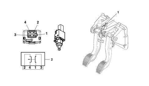
1 - Brake switch on pedal assembly
2 - Switch wiring diagram
Position of switch 1-3 "N.C." (pedal in rest position)
Position of switch 2-4 "N.A." (pedal pressed)
Reversing lights
The vehicle is equipped with two reversing lights located in the rear light clusters on the boot (moving part).
The activationof the rear light clusters is managed by a special switch on the outside of the gearbox casing which is pressed each time reverse gear is engaged via the gear lever on the manual version.
As far as the 6 speed automatic transmission version is concerned (1.9 JTD 16v / 2.4 JTD 20v), the reversing lights are activated when reverse gear is engaged (position R of the gear lever) and the automatic transmission control unit sends an earth signal to the specific relay for the function.
On the 5 speed automatic transmission version (2.2 Petrol), the reversing lights are activated when reverse gear is engaged (position R of the gear lever) by means of the special switch on the gear lever sensor unit.l
The signal that the reversing lights have come on is managed by the Body Computer which forwards the information via a discreet signal to the steering column switch unit for the automatic operation of the rearscreen wiper, to the parking sensors control unit, to the electrochromic interior mirror and to the driving position node for the adjustment memorized for the passenger side door mirror.
Direction indicators/hazard warning lights
The vehicle is equipped with six direction indicators located, in the front headlamps, in the rear light clusters (fixed part) and in the mud guards; they are activated by raising or lowering the special left steering column switch unit lever. The function is activated with the ignition key turned to ON.
The hazard lights (right and left indicators operated simultaneously) are activated by a button on the gear lever trim on the tunnel. The LED in the back of the control button also comes on synchronized with the flashing of the exterior lights and the activation of the blinker to signal that the alarm has come on during both the activation and the deactivation.
The engagement of the direction indicators / hazard warning lights is managed by the Body Computer which also controls the flashing frequency which is sent to the other nodes via the CAN. In this way the two direction indicator warning lights in the instrument panel are also switched on; in addition, the system provides a low frequency acoustic signal in conjunction with the activation of the lights.
Fog lights
The vehicle is equipped with fog lights housed in the front bumper and activated by the special button in the panel to the left of the steering wheel. When the function is activated the warning light in the instrument panel comes on.
A special relay managed by the Body Computer controls the activation of the fog lights; the function can be activated in certain conditions, namely: key in ON position enablement, control signal coming from the special switch and side lights on.
If the side lights are switched off, the fog lights are also turned off; switching the side lights on later on does not involve the activation of the fog lights which will be restored when the appropriate button is pressed again.
If the key is switched off (OFF position) and then switched back to the ON position, the button must be activated again to turn on the fog lights.
Rear foglamps
The vehicle is equipped with two very bright rear fog lights located in the rear light clusters (moving part). Like for the fog lights, the function is activated by the special button located in the panel to the left of the steering wheel; when the lights are on the warning light in the instrument panel comes on.
A special relay managed by the Body Computer controls the activation of the rear fog lamps; the function can be activated in certain conditions, namely: key in ON position enablement, control signal coming from the special switch and dipped headlamps or fog lights on.
If the dipped headlamps or fog lights are switched off, then the rear fog lamps are also turned off; switching the dipped headlamps or the fog lights on later on does not involve the activation of the rear fog lamps which will be restored when the appropriate button is pressed again.
If the key is switched off (OFF position) and then switched back to the ON position, the button must be activated again to turn on the rear fog lamps.
Lights check
This function makes it possible check the lighting system for the entire vehicle, in particular:
- side lights and no. plate lights
- direction indicators
- brake lights
- rear fog lamps
The following is checked for each of the circuits:
- circuit open or bulb missing
- short-circuit to earth (bulb s.c. or wiring s.c. to earth)
- short circuit to battery voltage (wiring short circuited to Vbatt.)
When one of the situations described above is ascertained, the Body Computer makes the failure status available to the CAN: the "exterior lighting fault" warning light lights up on the instrument panel and the information is simultaneously shown on the display.
In addition, the continuity of the protective fuse for the switch on the brake pedal is checked for the brake lights If there is a failure with one of the bulbs for the rear side lights, with the side lights on, the brake light on the same side comes on dimly to simulate the brightness of the side light.
The system also detects any fault in the dusk sensor switching on the general failure warning light in the instrument panel if necessary and, at the same time, the information is shown on the display.
In the direction indicators failure condition, the lights failure warning light in the instrument panel is lit up and the flashing frequency for the corresponding visual warning and the acoustic warning is increased; the flashing frequency of the exterior direction indicators and the LED in the hazard warning lights button, on the other hand, remains unchanged.
Headlamp alignment adjustment
The adjustment of the headlamp light beam according to the load is carried out by means of a special device (located inside the front light cluster) which tilts it appropriately, lowering the light beam if the vehicle is heavily laden and raising it if the load lessens. The device is enabled only with the dipped beams on.
A button, situated in the panel to the left of the steering wheel, controls the function, allowing the adjustment of the headlamps in four positions from 0 to 3.
| Position | Condition |
|---|---|
| 0 | Normal motion |
| 1 | 5 seats occupied |
| 2 | Boot loaded |
| 3 | Vehicle fully laden |
These four positions are produced by acting on the upper part of the headlamp alignment button to direct the light beam upwards (positions 3, 2, 1, 0) and on the lower part to move it downwards (positions 0,1, 2, 3); the setting is memorized and shown in the instrument panel display.
When the dipped headlamps are switched off, the movement is inhibited and the current position of the headlamp parabolas is maintained; when the dipped headlamps are switched on again, the headlamp alignment symbol will come on in the display with the number of the last position memorized.
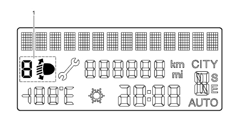
1 - Alignment position indicator
The headlamp alignment correcter function is managed directly by the Instrument Panel Node; if there is a fault in the system the headlamps assume a configuration that avoids oncoming vehicles from being dazzled.
GAS DISCHARGE HEADLAMPS
Introduction
The lighting devices occupy a fundamental position amongst the vehicle''s active safety systems.
The need to improve the performance of current systems based on halogen bulbs in terms of the light flow emitted and the spectral distibution and life of the bulb has led to the development of gas discharge headlamps technology and the devices that allows its operation on the vehicle.
There are basically three types of advantage from the development of this technology:
- the increased light efficiency allows a reduction in the absorption of electrical energy;
- the bulb lasts, on average, twice as long as a halogen bulb.
The technology of gas discharge headlamps has led to the development of a series of devices that include:
- xenon bulbs;
- optics (reflective surface of the headlamp);
- control electronics, comprising the igniter and the ballast;
- automatic light beam alignment correction.
Light cluster assembly
Every light cluster includes the components necessray for the operation of the discharge bulb (bulb, igniter, control unit, dipped headlamp alignment control motor): the traditional components are also present (side lights, direction indicators).
Section of headlamp by gas discharge bulb.
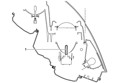
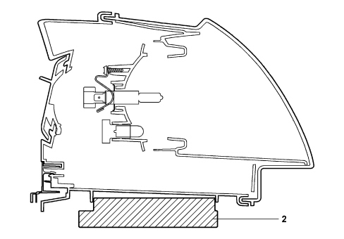
1 - Gas discharge bulb/igniter
2 - Ballast control unit
The lamp contains the following bulbs:
- W5W Blue Vision Long Life bulb (side lights function)
- PY21W Silver bulb (front direction indicators function)
- H1 55W bulb (main beam headlamps function)
- D1S (OSRAM) bulb 35W (dipped/main beam headlamps function)
The vehicle is equipped with a control unit for switching on and checking each headlamp, one right and one left, which are activated when the dipped headlamps function is requested controlled by the steering column switch unit turning the ring nut two positions. The CPS (left headlamp control unit) and CPD (right headlamp control unit) control units switch the gas discharge bulbs on and off at the times defined by the software and in accordance with international legislation.
The CPS is the master control unit, whilst the CPD performs the slave role.
The CPS acquires the command for the dipped headlamps, the vehicle speed VSO and the signals from the potentiometers located on the wheel axles. Depending on the inputs, the CPS directly controls the switching on of the left front headlamp (dipped headlamps) and similarly the CPD via the serial line. As a result, the CPD manages its own headlamp.
The potentiometers on the wheel axles are used by the CPS for managing the headlamp alignment for both headlamps (directly for the left one and via the CPD for the right one).
If there is a fault, the CPS positions the headlamps so that oncoming vehicles are not dazzled.
The CPS carries out the fault diagnosis for the sub-system (CPS + CPD and the potentiometers on the axles) and memorizes the faults.
The view of the connector and the pin out is illustrated below.
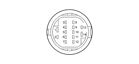
| Pin | Function |
|---|---|
| 1 | Dipped headlight |
| 3 | Main beam headlight |
| 4 | Side light |
| 5 | Direction indicator |
| 9 | INT power supply |
| 10 | Speedometer signal (for left headlamp only) |
| 11 | Diagnostic line K |
| 12 | Master/Slave serial line |
| 13 | Electronic earth |
| 14 | Bulb earth |
Xenon bulb
Xenon bulbs consist of a bulb containing two electrodes spaced a few millimetres apart and filled with low pressure xenon gas.
The emission of light is produced by an arc between the two electrodes which is maintained during the operation of the bulb; this process is similar to what takes place in neon lights.
Unlike the latter however, in automotive applications, it is unthinkable to have to wait for a few minutes before the process stabilizes, therefore the light cluster has an electronic control device (control unit) that allows operation, as far as the warming up times are concerned, comparable to traditional headlamps.
View of D1S (OSRAM) 35W gas discharge bulb

Pilot electronics
Each bulb is controlled by pilot electronics comprising two devices: the ballast control unit and the igniter.
The ballast has the function of converting the low voltage direct current coming from the battery into a medium tension alternating current and of controlling the operation of the sub-system in closed loop.
For this purpose the ballast control unit is capable of controlling the voltage-current during the switching on stage in an excellent manner and it is capable of providing the bulb with the power required for operating when it is warmed up.
The igniter is controlled by the ballast and is capable of producing the high tension (max 25 KV) required for te arc between the electrodes.
The ballast for the left headlamp performs the MASTER function: it is the one that receives the signals from the sensors, processes them and transmits them to the ballast for the right SLAVE headlamp.
OPERATION
The operation of a xenon bulb is divided into four stages.
Ignition
During this stage the ballast produces a voltage capable of causing the engagement of a suitable device located in the igniter. A step-up transformer circuit transfers the suitably amplified excess voltage to the bulb thereby causing a discharge between the electrodes.
Take-over (arc maintenance)
During this stage (lasting several seconds) the bulb receives the excess power supply necessary for producing the rapid evaporation of the metallic halides contained in the bulb in order to guarantee that the operating brightness is reached quickly. In these conditions the bulb produces a light flash that is twice the intensity of normal for a period of about 100 microseconds.
Warm up
For a period of about two minutes, the ballast regulates the light intensity determining the physical state of the bulb from its impedance properties (closed loop control).
Steady state
The light beam is controlled continuously in closed loop in the steady state.
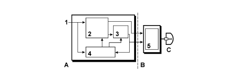
1 - Power supply (12V)
2 - High tension generator
3 - Square wave generator
4 - CPU
5 - Step-up transformer circuit
A - Ballast
B - Igniter
C - Bulb
On the new version the bulb forms one piece with the igniter.
Main beam management
The xenon bulbs have a dual function: dipped headlamp and stable main beam headlamp.
The switching of the two functions takes place by means of an actuator located in the lower part of the elliptical module.
The "flasher" function, on the other hand, allows the additional main beam headlamp bulbs only to come on.
The Body Computer controls the power supply for the additional main beam headlamps and the electronics inside the headlamps (dipped/main beam headlamps xenon bulb switching motor) sending an earth signal to the engine compartment junction unit which energizes the specific relay for the function.
Activation of the high beams in flashing mode is managed directly by the engine compartment control unit by means of two signals sent to the supplementary halogen bulbs (55W) built into the headlamps. These bulbs are active in fixed mode, but the high beam control (via xenon bulbs) renders them secondary.
Automatic headlamp alignment correcter
As a result of the brightness of the bulb light beam, the vehicle must be equipped with an automatic headlamp alignment correcter to prevent the driver''s of oncoming vehicles being dazzled.
The device intervenes in certain conditions:
- static type, due to the distribution of the load;
- dynamic type, due to acceleration and deceleration.
The automatic correcter also guarantees improved driving comfort because the area lit is kept stable and your eyes do not have to constantly adapt to the variations in the lighting.
This automatic device is managed by a stepping actuator and two load sensors connected to the front and rear suspension, on the left hand side.
The correction in this case is carried out through the signal for the load sensors which periodically supply the vehicle alignment conditions.
When the key is in the ON position, the control unit is activated and completely resets the headlamps to the exact distance calculated depending on the vehicle load which consists of lowering it and then repositioning it exactly.
The adjustment does not take place immediately, but is filtered over a period of time to prevent undesired corrections (e.g. pothole or unmade roads).
This correction is also made with the lights off, so that the moment the light beam is switched on it is already correctly positioned.
The sensors are fastened to the bodyshell, whilst a lever positioned on them follows the movement of the suspension; they receives a power supply from the headlamp control unit and provide a linear output signal proportional to the position of the suspension in relation to the bodyshell.
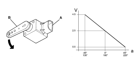
A - Part fastened to the bodyshell
B - Part fastened to the suspension linkage
a - Lever angle
V - Sensor output signal voltage
An adjustment actuator inside the light cluster produces the movement of the headlamp parabola, transforming rotary motion into linear motion.
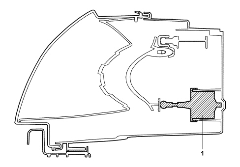
1 - Stepping adjustment motor
Self-diagnosis
The electronics that manage the system have an autodiagnostic function that continuously checks operation.
The control unit carries out continuous self-diagnosis of system operation. More specifically:
- it detects and stores faults
- it recognises the various components and the fault type
The faults memorized in the control unit can be analyzed using the Examiner or other diagnostic equipment.
Recovery
The management logic for the autodiagnostic function also has a recovery function which, if errors are detected, automatically lowers the light beam so that it is not dazzling under any circumstances and guarantees sufficient lighting for driving safely until a Service Centre can be reached.
Zeroing
If one of the system components is replaced (headlamp, sensor, etc.) a self-learning procedure must be carried out, connecting to the diagnostic equipment, which makes it possible to autoamtically reset the system which should recognize the the position of the headlamp correctly aligned in position 0 from where the various adjustments can be set.
Light beam manual adjustment
In order to carry out the adjustment of the light beam manually, the two ring nus on the light cluster can be used: the ring nut on the outside of the unit is designed for the horizontal adjustment, the middle one for the vertical adjustment.
The vertical adjustment takes place both by using the specific ring nut and also by turning the horizontal adjustment ring nut, thereby allowing the angular correction of the light beam.
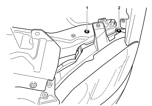
1 - Vertical adjustment ring nut
2 - Horizontal/angular adjustment ring nut
Parts & tools for this job For 2005 Fiat Croma
- PARTReplacement bulbsSearch: Fiat Croma 2005 bulbs
- TOOLDigital multimeterSearch: automotive digital multimeter
Links open Amazon search results in a new tab. As an Amazon Associate I earn from qualifying purchases.