
Engine - position on stand and remove
- Make
- Fiat
- Model
- Croma Factory Service Manual
- Year
- 2005–2010
- Section
- Engine and power unit › Engine - position on stand and remove
ENGINE - POSITION ON STAND AND REMOVE
Removing
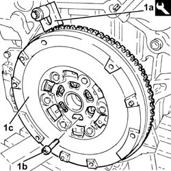
1. With the flywheel lock (1a) fitted, undo the bolts (1b) and remove the flywheel (1c).
| Tool | Description | Function | Validity |
|---|---|---|---|
| 1860846000 | Counter-torque | Flywheel lock |
The bolts fixing the flywheel are pre-treated with sealant, therefore they should be replaced each time they are removed.
1. Remove the manual gearbox centering bushes from the engine block.
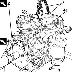
2. Fit the tool on the engine block.
| Tool | Description | Function | Validity |
|---|---|---|---|
| 1871000000 | Bracket | Positioning engine on overhaul stand |
3. Apply suitable chains to the engine and support it using a suitable hydraulic hoist.
4. Place the engine (4a) on the overhaul stand (4b) using the tool fitted previously.
| Tool | Description | Function | Validity |
|---|---|---|---|
| 1871000000 | Overhaul stand | Engine support for overhauling |
Refitting
- Remove the engine from the overhaul stand.
| Tool | Description | Function | Validity |
|---|---|---|---|
| 1871000000 | Overhaul stand | Engine support for overhauling |
- Remove the harness and the hydraulic hoist supporting the engine.
- Remove the tool from the engine block.
| Tool | Description | Function | Validity |
|---|---|---|---|
| 1871000000 | Bracket | Positioning engine on overhaul stand |
- Place the manual gearbox centering bushes on the engine block.
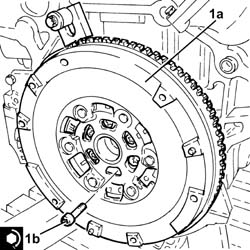
1. Place the flywheel (1a) in its housing and secure it tightening the new bolts (1b) to the recommended torque.
| Component | Fastening | dia | Value (daNm) | Validity |
|---|---|---|---|---|
| Engine flywheel | Bolt (to be replaced) | (engine crankshaft side) 6.0 + 30° + 15° | 2.2 |
Secure and support the engine using a hydraulic lift fitted with chains.
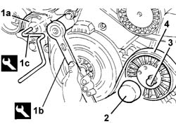
1. Adjust the moving tensioner (1a) for the single drive belt using the spanner (1b), then insert the tool (1c) in the opening in the tensioner.
| Description | Code | Function | |
|---|---|---|---|
| 1b | Spanner | 1.860.966.000 | Tensioning auxiliary shaft belt |
| Description | Code | Function | |
|---|---|---|---|
| 1c | Lock | 1.870.645.000 | Tensioning auxiliary shaft belt |
2. Remove the protective plug for the auxiliar shaft drive belt cam tensioner.
3. Undo the bolt retaining the cam tensioner.
4. Remove the auxiliary shaft drive belt.
1. Undo the fixing nut (1a) and disconnect the electrical connection from the alternator (1b).
| Description | Connector | |
|---|---|---|
| 1b | Alternator | A010A |
| Description | Connector | |
|---|---|---|
| 1b | Alternator | A010B |
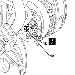
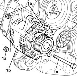
1. Undo the bolts (1a) and remove the alternator (1b).
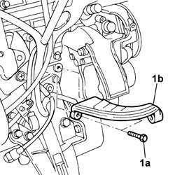
1. Undo the fixing bolts (1a) and remove the alternator upper mounting bracket (1b).
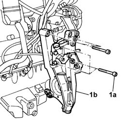
1. Undo the bolts (1a) and remove the rear engine support (1b).
1. Disconnect the electrical connection for the engine oil level sensor.
| Description | Connector | |
|---|---|---|
| 1 | Engine oil level sensor | K032 |
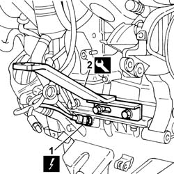
2. Fit the rear bracket for positioning the engine on the overhaul stand.
| Description | Code | Function | |
|---|---|---|---|
| 2 | Brackets | 1.861.001.039 | Engine support on overhaul stand |
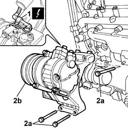
1. Disconnect the electrical connection for the air conditioning compressor.
| Description | Connector | |
|---|---|---|
| 1 | Air conditioning compressor engagement electro-magnet | L020 |
2. Undo the bolts (2a) and remove the air conditioning compressor and front engine support assembly (2b).
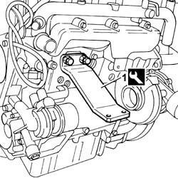
1. Fit the front bracket for positioning the engine on the overhaul stand.
| Description | Code | Function | |
|---|---|---|---|
| 1 | Brackets | 1.861.001.039 | Engine support on overhaul stand |
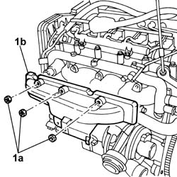
1. Undo the fixing nuts (1a) and remove the heat shield (1b) for the exhaust manifold.
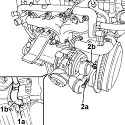
1. Open the band (1a) and disconnect the fluid return pipe from the turbocharger (1b).
2. Undo the connector (2a) and disconnect the oil supply pipe (2b) to the turbocharger from the crankcase.
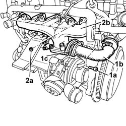
1. Undo the bolts (1a) fixing the rigid EGR pipe (1b) to the exhaust manifold and remove the gasket (1c).
2. Undo the nuts (2a) securing the exhaust manifold (2b) to the cylinder head.
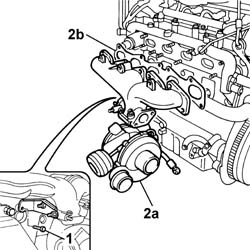
1. Undo the bolt fixing the turbine mounting bracket to the crankcase.
2. Remove the exhaust manifold and turbocharger assembly (2a) and the metal gasket (2b).
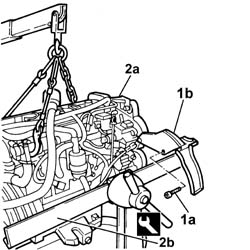
1. Undo the fixing bolt (1a) and remove the power assisted pump protective shield (1b).
2. Using a hydraulic lift, place the engine (2a) on the overhaul stand (2b).
| Description | Code | Function | |
|---|---|---|---|
| 2b | Overhaul stand | 1.861.000.000 | Support the engine |
It is possible to use the following stand as an alternative to the overhaul stand mentioned above:
| Description | Code | Function | |
|---|---|---|---|
| Overhaul stand | 1.871.001.000 | Support the engine |
Fasten the mounting brackets to the overhaul stand.
Release the engine from the hydraulic lift.
Proceed as follows to remove the engine from the overhaul stand.
Secure and support the engine using a hydraulic lift fitted with chains.
Undo the fastenings and remove the engine complete with mounting brackets.
Remove the brackets for positioning the engine on the overhaul stand from the crankcase.
| Description | Code | Function | |
|---|---|---|---|
| Brackets | 1.861.001.039 | Engine support on overhaul stand |
1. Place a new metal gasket (1a) in position and then fit the exhaust manifold and turbine assembly (1b).
2. Tighten the bolt fixing the turbine mounting bracket to the crankcase.
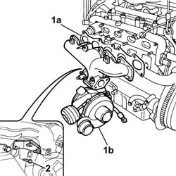
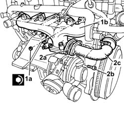
1. Tighten the nuts (1a) fixing the exhaust manifold (1b) to the cylinder head and check the torque.
| Value daNm | Fastening | Component | Ø | |
|---|---|---|---|---|
| 1a | 2.5 | Nut | EXHAUST MANIFOLD/S | M8 |
2. Place the new gasket (2a) in position and tighten the bolts (2b) fixing the rigid EGR pipe (2c) to the exhaust manifold/turbine tightening to torque.
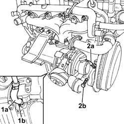
1. Connect the oil return pipe from the turbocharger (1a) and secure it using the band (1b).
2. Connect the turbocharger oil supply pipe (2a) to the crankcase and tighten the connector (2b) to the recommended torque.
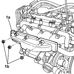
1. Place the exhaust manifold heat shield (1a) in position and tighten the fixing nuts (1b) checking the torque.
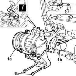
1. Place the air conditioning compressor and front engine support assembly (1a) in position and tighten the fixing bolts (1b) to the recommended torque.
2. Connect the electrical connection for the air conditioning compressor.
| Description | Connector | |
|---|---|---|
| 2 | Air conditioning compressor engagement electro-magnet | L020 |
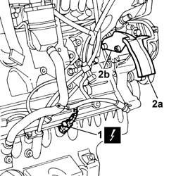
1. Connect the electrical connection for the engine oil level sensor.
| Description | Connector | |
|---|---|---|
| 1 | Engine oil level sensor | K032 |
2. Fit the protective shield (2a) for the power assisted steering pump in place and tighten the fixing bolt (2b).
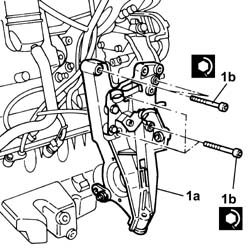
1. Fit the rear engine support (1a) in place and tighten the fixing bolts (1b) to the recommended torque.
| Value daNm | Fastening | Component | Ø | |
|---|---|---|---|---|
| 1b | 5 | Bolt | RIGID REAR SUPPORT POWER UNIT | M10 X 1.25 |
| Value daNm | Fastening | Component | Ø | |
|---|---|---|---|---|
| 1b | 2.5 | Bolt | RIGID REAR SUPPORT POWER UNIT | M8 |
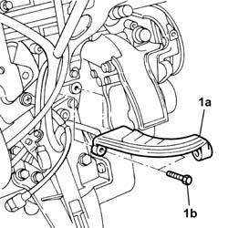
1. Fit the upper alternator mounting bracket (1a) and tighten the fixing bolts (1b) to the recommended torque.
1. Fit the alternator (1a) in place and tighten the fixing bolts (1b) to the recommended torque.
| Value daNm | Fastening | Component | Ø | |
|---|---|---|---|---|
| 1b | 5 | Nut | ALTERNATOR ASSEMBLY | M10 X 1.25 |
| Value daNm | Fastening | Component | Ø | |
|---|---|---|---|---|
| 1b | 7 | Nut | ALTERNATOR ASSEMBLY | M12 X 1.25 |
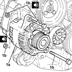
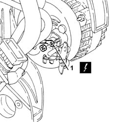
1. Connect the electrical connection to the alternator.
| Description | Connector | |
|---|---|---|
| 1 | Alternator | A010A |
| Description | Connector | |
|---|---|---|
| 1 | Alternator | A010B |
Place the engine components single belt in position using a spanner on the moving tensioner.
Release the engine from the hydraulic lift.
Removing
1. Fit the flywheel lock.
| Tool | Description | Function | Validity |
|---|---|---|---|
| 1860846000 | Counter-torque | Flywheel lock |
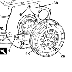
2. Undo the bolts (2a) and remove the engine flywheel (2b).
The bolts fixing the flywheel are pre-treated with sealant, therefore they should be replaced each time they are removed.
- Remove the flywheel lock.
3. Undo the bolts (3a) and remove the flywheel guard (3b).
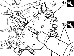
1. Position the engine on the support tools (1a) and overhaul tools (1b).
| Tool | Description | Function | Validity |
|---|---|---|---|
| 1871000000 | Bracket | Positioning engine on overhaul stand |
| Tool | Description | Function | Validity |
|---|---|---|---|
| 1871000000 | Overhaul stand | Engine support for overhauling |
Refitting
- Remove the engine from the tools used for supporting it.
| Tool | Description | Function | Validity |
|---|---|---|---|
| 1871000000 | Overhaul stand | Engine support for overhauling |
| Tool | Description | Function | Validity |
|---|---|---|---|
| 1871000000 | Bracket | Positioning engine on overhaul stand |
- Place the rear flywheel guard in its housing and secure it using the bolts.
- Place the flywheel lock in its housing.
| Tool | Description | Function | Validity |
|---|---|---|---|
| 1860846000 | Counter-torque | Flywheel lock |
- Place the flywheel in its housing and secure it by tightening the new bolts to the recommended torque.
| Component | Fastening | dia | Value (daNm) | Validity |
|---|---|---|---|---|
| Engine flywheel | Bolt (pretreated to replace) | M12 | (crankshaft side) 14.4 - 17.6 | 1.9 JTD 16v 1.9 JTD 8v |
- Remove the flywheel lock.
- Unscrew the bolts and remove the engine flywheel, then refer to
Op. 1024B22 ENGINE FLYWHEEL - R.R WITH CLUTCH REMOVED FOR VERSIONS WITH MANUAL GEARBOX
1. Undo the bolts (1a) and remove the flywheel guard (1b).
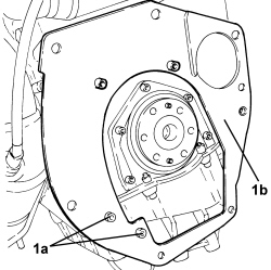
1. Fit the support (1a) on the engine block (1b).
| Tool | Description | Function | Validity |
|---|---|---|---|
| 1871000000 | Overhaul stand | Overhaul engine |
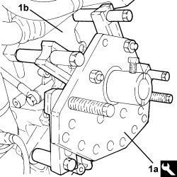
1. Using the tool and a hydraulic lift, place the engine on the overhaul stand.
| Tool | Description | Function | Validity |
|---|---|---|---|
| 1871000000 | Overhaul stand | Overhaul engine |
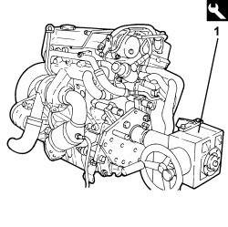
- Support the engine using the tools and a hydraulic lift.
- Undo the bolts fixing the engine block to the overhaul stand support.
- Fit the flywheel guard and secure it using the bolts.
- Fit the engine flywheel with reference to
Op. 1024B22 ENGINE FLYWHEEL - R.R WITH CLUTCH REMOVED FOR VERSIONS WITH MANUAL GEARBOX
Parts & tools for this job For 2005 Fiat Croma
- PARTEngine gasket setSearch: Fiat Croma 2005 engine gasket set
- TOOLTorque wrenchSearch: 3/8 inch torque wrench
- TOOLFeeler gauge setSearch: feeler gauge set
Links open Amazon search results in a new tab. As an Amazon Associate I earn from qualifying purchases.