
Air chamber - r.r.
- Make
- Fiat
- Model
- Croma Factory Service Manual
- Year
- 2005–2010
- Section
- Inlet and exhaust manifolds › Air chamber - r.r.
AIR CHAMBER - R.R.
Removing
- Position the vehicle on a lift.
- Make sure that the ignition key is in the OFF position, then disconnect the battery terminal (-).
| Description | Connector | |
|---|---|---|
| Battery | See A001 BATTERY |
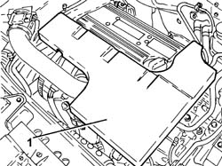
1. Remove the sound insulation cover fastened to the engine by three pins.
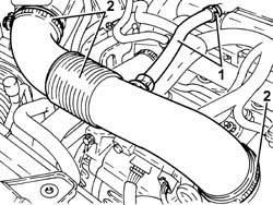
1. Loosen the band and disconnect the engine oil vapour recovery pipe from the cylinder head cover.
2. Loosen the bands and remove the air supply hose from the air flow meter to the throttle casing.
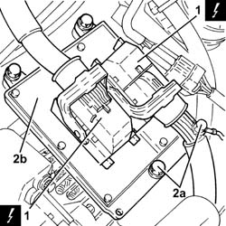
1. Disconnect the electrical connections from the injection/ignition system control unit.
| Description | Connector | |
|---|---|---|
| 1 | Engine management control unit | See M010 ENGINE MANAGEMENT CONTROL UNIT |
2. Undo the bolts (2a) and remove the injection/ignition system control unit (2b).
One of the bolts also secures the earth lead.
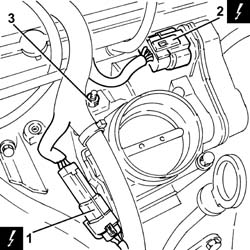
1. Disconnect the engine coupling.
| Description | Connector | |
|---|---|---|
| 1 | Engine cables/engine services cable coupling | See D029 ENGINE CABLES/ENGINE SERVICES CABLE COUPLING |
2. Disconnect the electrical connection from the throttle casing with D.V.L.
| Description | Connector | |
|---|---|---|
| 2 | Integrated throttle casing actuator | See N075 INTEGRATED THROTTLE CASING ACTUATOR |
3. Loosen the nut fixing the electric wiring mounting bracket.
1. Undo the bolts (1a) and remove the throttle casing with D.V.L. (1b).
- Remove the air chamber gasket.
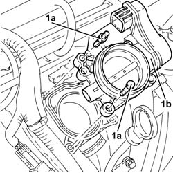
1. Disconnect the electrical connection from the air pressure sensor.
| Description | Connector | |
|---|---|---|
| 1 | Absolute pressure sensor | See K048 ABSOLUTE PRESSURE SENSOR |
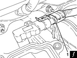
1. Undo the bolt (1a) and remove the engine oil dipstick tube (1b) assembly after having released it from the electrical wiring.
2. Undo the bolt fixing the electrical wiring mounting bracket to the air chamber.
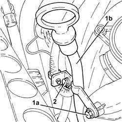
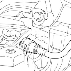
1. Disconnect the quick-release fitting for the fuel vapour recovery pipe, air chamber side.
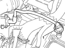
1. Disconnect the quick-release fitting for the brake servo vacuum intake pipe, air chamber side.
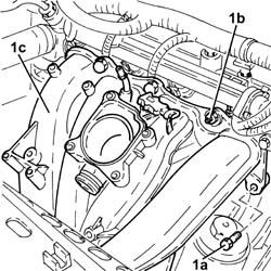
1. Undo the bolts (1a) and the nuts (1b) and remove the air chamber (1c).
- Remove the seals.
Refitting
- Clean the contact surfaces
- Place the new gaskets in their housings on the air chamber.
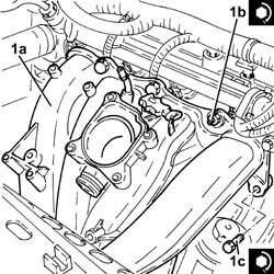
1. Position the air chamber (1a) in its housing and secure it tightening the nuts (1b) and the bolts (1c) to the recommended torque.
| Component | Fastening | dia | Value (daNm) | Validity |
|---|---|---|---|---|
| Air chamber | Nut | M6 x 1 | (cylinder head side) 0.9 | 2.2 |
| Component | Fastening | dia | Value (daNm) | Validity |
|---|---|---|---|---|
| Air chamber | Bolt | M6 x 1 | (cylinder head side) 0.9 | 2.2 |
- Connect the quick-release fitting for the brake servo vacuum intake pipe, air chamber side.
- Connect the quick-release fitting for the fuel vapour recovery pipe, air chamber side.
- Tighten the bolt fixing the electrical wiring mounting bracket to the air chamber.
- Place the engine oil dipstick pipe back in its housing and fasten it with the bolt.
- Fasten the electrical wiring to the engine oil dipstick pipe.
- Connect the electrical connection to the air pressure sensor.
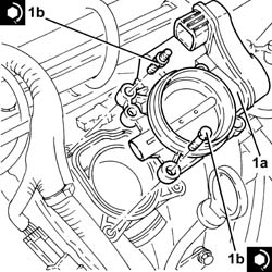
1. Place the throttle casing integrated with D.V.L. (1a), complete with gasket, back in its housing and secure it tightening the bolts (1b) to the recommended torque.
| Component | Fastening | dia | Value (daNm) | Validity |
|---|---|---|---|---|
| Throttle body built into DVL | Bolt | M6 x 1 | (air chamber side) 0.9 | 2.2 |
- Tighten the nut fixing the electric wiring mounting bracket.
- Connect the electrical connection to the throttle casing with D.V.L.
- Connect the engine coupling.
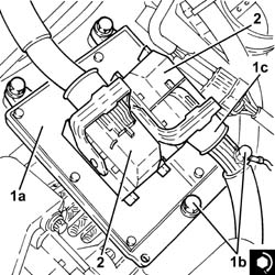
1. Place the injection/ignition system control unit (1a) in its housing and secure it tightening the bolts (1b) to the recommended torque.
One of the bolts also secures the earth lead (1c).
| Component | Fastening | dia | Value (daNm) | Validity |
|---|---|---|---|---|
| Injection/ignition system control unit | Bolt | M6 x 1 | (air chamber side) 0.9 | 2.2 |
2. Connect the electrical connections to the injection/ignition system control unit.
- Place the air supply hose from the air flow meter to the throttle casing back in its housing and secure it using the bands.
- Connect the engine oil vapour recovery pipe to the cylinder head cover and secure it using the band.
- Place the sound insulation cover back in its housing and secure it to the engine using the three pins.
- Connect the negative battery terminal.
- Remove the vehicle from the lift.
Parts & tools for this job For 2005 Fiat Croma
- PARTExhaust gasketSearch: Fiat Croma 2005 exhaust gasket
- TOOLPenetrating oilSearch: penetrating oil
- TOOLOBD2 scannerSearch: OBD2 scanner
Links open Amazon search results in a new tab. As an Amazon Associate I earn from qualifying purchases.