
Exhaust manifold heat shield - r+r
- Make
- Fiat
- Model
- Croma Factory Service Manual
- Year
- 2005–2010
- Section
- Inlet and exhaust manifolds › Exhaust manifold heat shield - r+r
EXHAUST MANIFOLD HEAT SHIELD - R+R
Removing
- Position the vehicle on a lift.
- Make sure that the ignition key is in the OFF position, then disconnect the battery terminal (-).
| Description | Connector | |
|---|---|---|
| Battery | See A001 BATTERY |
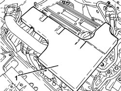
1. Remove the soundproof cover secured to the engine by three pins.
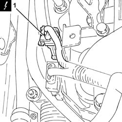
1. Disconnect the electrical connection for the front Lambda sensor to the catalytic converter.
| Description | Connector | |
|---|---|---|
| 1 | Lambda sensor on catalyzer | See K017 LAMBDA SENSOR ON CATALYZER |
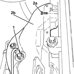
1. Unscrew and remove the front lambda sensor from the catalytic converter.
2. Undo bolts (2a) and remove the exhaust manifold heat shield (2b).
Refitting
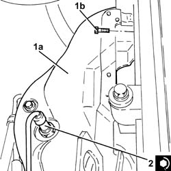
1. Place the exhaust manifold heat shield (1a) back in its housing and secure it using the bolts (1b).
2. Position the front Lambda sensor in its housing on the catalytic converter and tighten it to the recommended torque.
| Component | Fastening | dia | Value (daNm) | Validity |
|---|---|---|---|---|
| Front Lambda sensor to catalytic converter | - (with special black grease) | M18 x 1.5 | (exhaust manifold with catalytic converter side) 4.0 | 2.2 |
- Connect the electrical connection for the front Lambda sensor to the catalytic converter.
- Refit the soundproofing cover in its seat and secure to the engine with the three pins.
- Connect the negative battery terminal.
- Remove the vehicle from the lift.
Removing
- Position the vehicle on a lift.
Op. 1016A10 SOUND-PROOFING COVER - R.R
Op. 5530B52 BATTERY SUPPORT/DRIP TRAY - R.R
Op. 1048B19 TURBOCHARGER AIR OUTLET HOSE -R.R.
Op. 1048A42 SLEEVE FROM FLOW METER TO TURBO CHARGER AIR INLET PIPE - R + R
Op. 7055B54 UNDER ENGINE PROTECTION/GUARD - R.R.
Op. 1048A50 TURBOCHARGER AIR INTAKE PIPE - R.R.
Op. 1048A10 AIR FILTER ASSEMBLY - R.R.
Op. 1084A16 OIL DIPSTICK PIPE - R.R
Op. 1088D24 WATER PUMP RIGID COOLANT INLET PIPE - R.R.
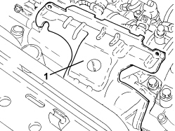
1. Remove the exhaust manifold heat shield.
Refitting
- Place the exhaust manifold heat shield in its housing.
Op. 1088D24 WATER PUMP RIGID COOLANT INLET PIPE - R.R.
Op. 1084A16 OIL DIPSTICK PIPE - R.R
Op. 1048A10 AIR FILTER ASSEMBLY - R.R.
Op. 1048A50 TURBOCHARGER AIR INTAKE PIPE - R.R.
Op. 7055B54 UNDER ENGINE PROTECTION/GUARD - R.R.
Op. 1048A42 SLEEVE FROM FLOW METER TO TURBO CHARGER AIR INLET PIPE - R + R
Op. 1048B19 TURBOCHARGER AIR OUTLET HOSE -R.R.
Op. 5530B52 BATTERY SUPPORT/DRIP TRAY - R.R
Op. 0010T20 ENGINE COOLANT - CHANGE
Op. 1016A10 SOUND-PROOFING COVER - R.R
- Remove the vehicle from the lift.
- On this version it is not possible to remove/refit the exhaust manifold heat shield on the car.
To perform this operation, remove/refit the power unit
Op. 1004B14 POWER UNIT WITH AUTOMATIC TRANSMISSION R + R
and then work at the bench, customising the engine service procedures for this operation.
Removing
Op. 1084A16 OIL DIPSTICK PIPE - R.R
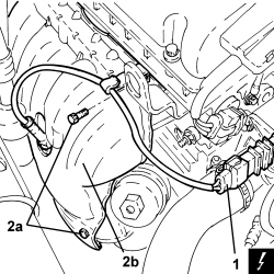
1. Disconnect the electrical connection for the front Lambda sensor to the catalytic converter.
| Description | Connector | |
|---|---|---|
| 1 | Lambda sensor on catalyzer | See K017 LAMBDA SENSOR ON CATALYZER |
2. Undo the upper and lower bolts (2a) securing the heat shield (2b) to the exhaust manifold and remove it.
Refitting
- Place the heat shield back in its housing and secure it to the exhaust manifold using the bolts.
- Connect the electrical connection for the front Lambda sensor to the catalytic converter.
Parts & tools for this job For 2005 Fiat Croma
- PARTExhaust gasketSearch: Fiat Croma 2005 exhaust gasket
- TOOLPenetrating oilSearch: penetrating oil
- TOOLOBD2 scannerSearch: OBD2 scanner
Links open Amazon search results in a new tab. As an Amazon Associate I earn from qualifying purchases.