
Water pump rigid coolant inlet pipe - r.r.
- Make
- Fiat
- Model
- Croma Factory Service Manual
- Year
- 2005–2010
- Section
- Engine cooling › Water pump rigid coolant inlet pipe - r.r.
WATER PUMP RIGID COOLANT INLET PIPE - R.R.
Removing
- Position the vehicle on a lift.
- Make sure that the ignition key is in the OFF position, then disconnect the battery terminal (-).
| Description | Connector | |
|---|---|---|
| Battery | See A001 BATTERY |
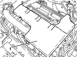
1. Remove the sound insulation cover fastened to the engine by three pins.
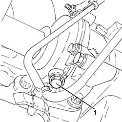
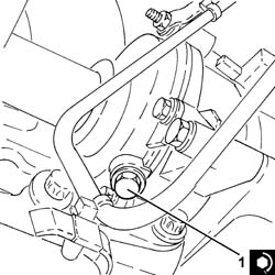
1. Undo the coolant drain plug in the water pump and drain the coolant.
Collect the coolant in a suitable container.
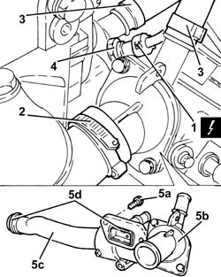
1. Disconnect the electrical connection from the engine coolant temperature sensor.
| Description | Connector | |
|---|---|---|
| 1 | Engine coolant temperature sensor/sender unit | See K036 ENGINE COOLANT TEMPERATURE SENSOR/SENDER UNIT |
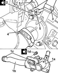
2. Loosen the collar and disconnect the upper coolant input sleeve to the radiator, thermostat side.
3. Loosen the bands and disconnect the coolant delivery and return pipes to the climate control system heater, thermostat side.
4. Undo the engine coolant temperature sensor and remove it.
The engine coolant temperature sensor is removed to gain access to one of the thermostat fixing bolts.
5. Undo the bolts (5a) and remove the thermostat (5b) complete with water pump rigid fluid inlet pipe (5c) and O-rings (5d).
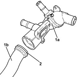
1. At the bench, separate the thermostat (1a) from the water pump rigid fluid inlet pipe (1b).
2. Remove the seal.
Refitting
1. Tighten the coolant drain plug to the water pump to the recommended torque.
Apply sealant to the plug before fitting it.
| Component | Fastening | dia | Value (daNm) | Validity |
|---|---|---|---|---|
| Drain plug on water pump | M20 x 1.5 | (water pump side) 2.0 | 2.2 |
- Assemble the rigid coolant inlet pipe and water pump complete with a new seal.
1. Place the thermostat (1a) complete with water pump rigid coolant inlet pipe (1b) and new O-rings (1c) back in its housing and secure it tightening the bolts (1d) to the recommended torque.
Apply (white) silicon grease to the O-rings.
| Component | Fastening | dia | Value (daNm) | Validity |
|---|---|---|---|---|
| Thermostat unit | Bolt | M6 x 1 | (engine crankcase side) 0.6 - 1.0 | 2.2 |
2. Place the engine coolant temperature sensor in its housing and tighten it to the recommended torque.
| Component | Fastening | dia | Value (daNm) | Validity |
|---|---|---|---|---|
| Engine coolant temperature sensor | M12 x 1.5 | (thermostat unit side) 2.1 | 2.2 |
3. Connect the coolant delivery and return pipes to the climate control system heater, thermostat side, and tighten the band.
4. Connect the upper coolant input sleeve to the radiator, thermostat side, and tighten the band.
5. Connect the electrical connection to the engine coolant temperature sensor.
- Place the sound insulation cover back in its housing and secure it to the engine using the three pins.
- Connect the negative battery terminal.
Op. 0010T20 ENGINE COOLANT - CHANGE
- Remove the vehicle from the lift.
Removing
- Position the vehicle on the lift.
Op. 1016A10 SOUND-PROOFING COVER - R.R
Op. 5530B52 BATTERY SUPPORT/DRIP TRAY - R.R
Op. 1048B19 TURBOCHARGER AIR OUTLET HOSE -R.R.
Op. 1048A42 SLEEVE FROM FLOW METER TO TURBO CHARGER AIR INLET PIPE - R + R
Op. 7055B54 UNDER ENGINE PROTECTION/GUARD - R.R.
Op. 1048A50 TURBOCHARGER AIR INTAKE PIPE - R.R.
Op. 1048A10 AIR FILTER ASSEMBLY - R.R.
Op. 1084A16 OIL DIPSTICK PIPE - R.R
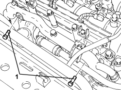
1. Undo the upper bolts fixing the exhaust manifold heat shield.
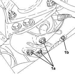
1. Undo the nuts (1a) and the bolt (1b) securing the exhaust manifold heat shield.
1. Undo the radiator coolant drain plug.
Collect the coolant in a suitable container.
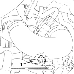
1. Loosen the band and disconnect the lower coolant inlet hose from the radiator, water pump rigid coolant inlet pipe side.
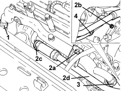
2. Undo the bolt (2a) and the nut (2b), loosen the band (2c) and move the system supply pipe (2d) sideways.
3. Loosen the band and disconnect the coolant outlet pipe from the coolant/exhaust gas heat exchanger for the EGR system, water pump rigid fluid inlet pipe side.
4. Loosen the band and disconnect the hose from the rigid coolant return pipe from the engine oil heat exchanger.
- Undo the bolt fixing the timing protective cover to the water pump rigid inlet pipe.
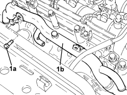
1. Undo the bolts (1a) and remove the water pump inlet pipe (1b).
- Remove the gasket.
Refitting
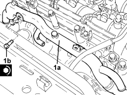
1. Place the water pump rigid inlet pipe (1a), complete with gasket, in position and secure it tightening the bolts (1b) to the recommended torque.
| Component | Fastening | dia | Value (daNm) | Validity |
|---|---|---|---|---|
| Water pump rigid inlet pipe | Bolt | M6 | (cylinder head side) 0.8 - 1.0 | 1.9 JTD 16v 1.9 JTD 8v |
- Tighten the bolt fixing the timing protective cover to the water pump rigid inlet pipe.
- Connect the hose to the engine oil heat exchanger rigid coolant return pipe and tighten the band.
- Connect the coolant outlet pipe from the coolant/exhaust gas heat exchanger for the EGR system, water pump rigid fluid inlet pipe side and tighten the band.
- Place the system supply pipe in its housing, connect it tothe water pump rigid coolant inlet pipe and tighten the band, the bolt and the nut.
- Connect the lower coolant inlet hose from the radiator, water pump rigid coolant inlet pipe side and tighten the band.
- Tighten the coolant drain plug to the radiator.
- Tighten the lower nuts and the bolt securing the exhaust manifold heat shield.
- Tighten the upper bolts fixing the exhaust manifold heat shield.
Op. 1084A16 OIL DIPSTICK PIPE - R.R
Op. 1048A10 AIR FILTER ASSEMBLY - R.R.
Op. 1048A50 TURBOCHARGER AIR INTAKE PIPE - R.R.
Op. 7055B54 UNDER ENGINE PROTECTION/GUARD - R.R.
Op. 1048A42 SLEEVE FROM FLOW METER TO TURBO CHARGER AIR INLET PIPE - R + R
Op. 1048B19 TURBOCHARGER AIR OUTLET HOSE -R.R.
Op. 5530B52 BATTERY SUPPORT/DRIP TRAY - R.R
Op. 0010T20 ENGINE COOLANT - CHANGE
Op. 1016A10 SOUND-PROOFING COVER - R.R
- Remove the vehicle from the lift.
- It is not possible on this version to remove-refit the water pump rigid inlet pipe on the vehicle.
To perform this operation, remove/refit the power unit
Op. 1004B14 POWER UNIT WITH AUTOMATIC TRANSMISSION R + R
and then work at the bench, customising the engine service procedures for this operation.
Removing
Op. 0010T20 ENGINE COOLANT - CHANGE
Op. 7055B54 UNDER ENGINE PROTECTION/GUARD - R.R.
Op. 1084A16 OIL DIPSTICK PIPE - R.R
Op. 1072C44 EXHAUST MANIFOLD HEAT SHIELD - R+R
Op. 1080B94 FRONT LAMBDA SENSOR TO WITH CATALYTIC CONVERTER - R.R
Op. 1072C16 EXHAUST MANIFOLD WITH CATALYTIC CONVERTER - R.R.
Op. 1084B36 ENGINE OIL FILTER MOUNTING AND HEAT EXCHANGER - R.R
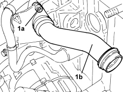
1. Undo the bolts (1a) and remove the water pump rigid inlet pipe (1b) complete with O-rings.
Refitting
- Place the water pump rigid inlet pipe, complete with new O-rings in position and secure it using the bolts.
Op. 1084B36 ENGINE OIL FILTER MOUNTING AND HEAT EXCHANGER - R.R
Op. 1072C16 EXHAUST MANIFOLD WITH CATALYTIC CONVERTER - R.R.
Op. 1080B94 FRONT LAMBDA SENSOR TO WITH CATALYTIC CONVERTER - R.R
Op. 1072C44 EXHAUST MANIFOLD HEAT SHIELD - R+R
Op. 1084A16 OIL DIPSTICK PIPE - R.R
Parts & tools for this job For 2005 Fiat Croma
- FLUIDCoolantSearch: Fiat coolant antifreeze
- PARTThermostatSearch: Fiat Croma 2005 thermostat
- TOOLCooling system pressure testerSearch: cooling system pressure tester
Links open Amazon search results in a new tab. As an Amazon Associate I earn from qualifying purchases.