
System cable bundle - r + r
- Make
- Fiat
- Model
- Doblò Factory Service Manual
- Year
- 2000–2010
- Section
- Petrol injection system › System cable bundle - r + r
System cable bundle - r + r
Removing
Position the vehicle on a lift.
Disconnect the negative battery lead.
| Description | Connector | |
|---|---|---|
| Battery | See A001 BATTERY |
Op. 1048A32 HOSE FROM AIR FILTER TO INTAKE MANIFOLD - R.R.
Op. 1056B82 INJECTION/IGNITION SYSTEM E.C.U. (ONE) - R + R
Remove the engine compartment junction unit cover, then release the control unit from the mount retaining clips.
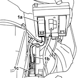
1. Disconnect engine compartment junction unit electrical connection (1a), disconnect the dashboard wiring harness connectors (1b) and (1c).
| Description | Connector | |
|---|---|---|
| 1a | Engine compartment junction unit | See B1F ENGINE COMPARTMENT JUNCTION UNIT ( ENGINE ) |
| Description | Connector | |
|---|---|---|
| 1b | Front/engine coupling | See D4A FRONT/ENGINE COUPLING ( FRONT ) |
| Description | Connector | |
|---|---|---|
| 1c | Front/engine coupling | See D4B FRONT/ENGINE COUPLING ( CONNECTORS ) |
Fold the wiring harness onto the power unit.
Release the wiring from the retaining clips in the battery holder area.
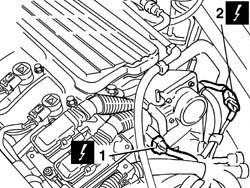
1. Disconnect the electrical connection for the throttle casing actuator.
| Description | Connector | |
|---|---|---|
| 1 | Integrated throttle casing actuator | See N75 INTEGRATED THROTTLE BODY ACTUATOR ( ENGINE ) |
2. Disconnect the electrical connection for the front Lambda sensor.
| Description | Connector | |
|---|---|---|
| 2 | Lambda sensor on pre-catalyzer | See K15 LAMBDA SENSOR ON PRE-CATALYZER ( ENGINE ) |
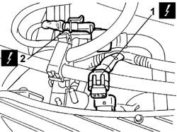
1. Disconnect the electrical connection for the intake air temperature/pressure sensor.
| Description | Connector | |
|---|---|---|
| 1 | Integrated air temperature sensor | See K43 INTEGRATED AIR TEMPERATURE SENSOR ( ENGINE ) |
2. Disconnect the electrical connection for the fuel vapour recovery solenoid valve.
| Description | Connector | |
|---|---|---|
| 2 | Fuel vapour recovery solenoid valve | See L10 FUEL VAPOUR RECOVERY SOLENOID VALVE ( ENGINE ) |
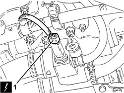
1. Disconnect the engine coolant temperature sensor on the thermostat unit.
| Description | Connector | |
|---|---|---|
| 1 | I.E. engine temperature sensor | See K45 COOLANT TEMPERATURE SENDER UNIT ( ENGINE ) |
Open the retaining collar and release the wiring.
1. Disconnect the electrical connection for the injectors.
| Description | Connector | |
|---|---|---|
| 1 | Injector coupling | See D81 INJECTOR JUNCTION ( COILS AND FUEL INJECTORS ) |
2. Disconnect the electrical connections for the ignition coils.
| Description | Connector | |
|---|---|---|
| 2 | Injector | See N070 INJECTOR |
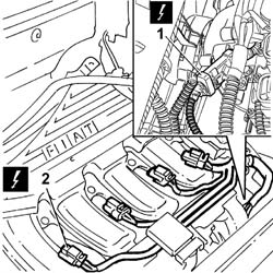
1. Unscrew bolts (1a) on the coil covers and disconnect earth leads (1b).
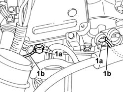
1. Disconnect the electrical connection for the speedometer sensor.
| Description | Connector | |
|---|---|---|
| 1 | Speedometer sensor | See K84 SPEEDOMETER SENSOR ( ENGINE ) |
2. Disconnect the electrical connection for the rear Lambda sensor.
| Description | Connector | |
|---|---|---|
| 2 | Lambda sensor on catalyzer | See K17 LAMBDA SENSOR ON CATALYZER ( ENGINE ) |
Open the wiring retaining band.
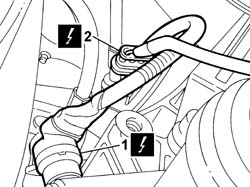
Raise the lift.
1. Undo the nuts (1a) and release the wiring harness protection (1b).
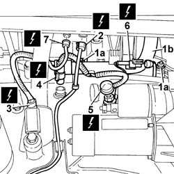
2. Disconnect the electrical connection for the rpm sensor.
| Description | Connector | |
|---|---|---|
| 2 | Rpm sensor | See K46 RPM SENSOR ( ENGINE ) |
3. Disconnect the electrical connection for the detonation sensor.
| Description | Connector | |
|---|---|---|
| 3 | Detonation sensor | See K50 DETONATION SENSOR ( ENGINE ) |
4. Disconnect the electrical connection for the engine oil pressure sensor.
| Description | Connector | |
|---|---|---|
| 4 | Insufficient engine oil pressure sensor (switch) | See K030 ENGINE OIL PRESSURE SENSOR (SWITCH) |
5. Disconnect the electrical connection for the starter motor.
| Description | Connector | |
|---|---|---|
| 5 | Starter motor | See A020 STARTER MOTOR |
6. Disconnect the electrical connection for the alternator.
| Description | Connector | |
|---|---|---|
| 6 | Alternator | See A010 ALTERNATOR |
7. Disconnect the electrical connection for the timing sensor.
| Description | Connector | |
|---|---|---|
| 7 | Timing sensor | See K47 TIMING SENSOR ( ENGINE ) |
Lower the lift and remove the wiring from the engine compartment.
Refitting
Place the system cable loom back in its housing and fasten it using the bands.
Connect the electrical connection for the timing sensor.
| Description | Connector | |
|---|---|---|
| Timing sensor | See K47 TIMING SENSOR ( ENGINE ) |
Connect the electrical connection for the alternator.
| Description | Connector | |
|---|---|---|
| Alternator | See A010 ALTERNATOR |
Connect the electrical connection for the starter motor.
| Description | Connector | |
|---|---|---|
| Starter motor | See A020 STARTER MOTOR |
Connect the electrical connection for the engine oil pressure sensor.
| Description | Connector | |
|---|---|---|
| Insufficient engine oil pressure sensor (switch) | See K030 ENGINE OIL PRESSURE SENSOR (SWITCH) |
Connect the electrical connection for the detonation sensor.
| Description | Connector | |
|---|---|---|
| Detonation sensor | See K50 DETONATION SENSOR ( ENGINE ) |
Connect the electrical connection for the rpm sensor.
| Description | Connector | |
|---|---|---|
| Rpm sensor | See K46 RPM SENSOR ( ENGINE ) |
Tighten the wiring harness protection nuts.
Connect the electrical connection for the rear Lambda sensor.
| Description | Connector | |
|---|---|---|
| Lambda sensor on catalyzer | See K17 LAMBDA SENSOR ON CATALYZER ( ENGINE ) |
Close the wiring retaining band.
Connect the electrical connection for the speedometer sensor.
| Description | Connector | |
|---|---|---|
| Speedometer sensor | See K84 SPEEDOMETER SENSOR ( ENGINE ) |
Position the earth leads and tighten the nuts to the coil covers.
Connect the electrical connections for the ignition coils.
| Description | Connector | |
|---|---|---|
| Injector | See N070 INJECTOR |
Connect the electrical connection for the injectors.
| Description | Connector | |
|---|---|---|
| Injector coupling | See D81 INJECTOR JUNCTION ( COILS AND FUEL INJECTORS ) |
Connect the engine coolant temperature sensor on the thermostat unit.
| Description | Connector | |
|---|---|---|
| I.E. engine temperature sensor | See K45 COOLANT TEMPERATURE SENDER UNIT ( ENGINE ) |
Reclose the engine wiring retaining band on the thermostat unit.
Connect the electrical connection for the fuel vapour recovery solenoid valve.
| Description | Connector | |
|---|---|---|
| Fuel vapour recovery solenoid valve | See L10 FUEL VAPOUR RECOVERY SOLENOID VALVE ( ENGINE ) |
Connect the electrical connection for the intake air temperature/pressure sensor.
| Description | Connector | |
|---|---|---|
| Integrated air temperature sensor | See K43 INTEGRATED AIR TEMPERATURE SENSOR ( ENGINE ) |
Connect the electrical connection for the front Lambda sensor.
| Description | Connector | |
|---|---|---|
| Lambda sensor on pre-catalyzer | See K15 LAMBDA SENSOR ON PRE-CATALYZER ( ENGINE ) |
Connect the electrical connection for the throttle casing actuator.
| Description | Connector | |
|---|---|---|
| Integrated throttle casing actuator | See N75 INTEGRATED THROTTLE BODY ACTUATOR ( ENGINE ) |
Close the wiring retaining collars on the battery holder.
Connect the dashboard wiring harness connectors.
| Description | Connector | |
|---|---|---|
| Front/engine coupling | See D4B FRONT/ENGINE COUPLING ( CONNECTORS ) |
| Description | Connector | |
|---|---|---|
| Front/engine coupling | See D4A FRONT/ENGINE COUPLING ( FRONT ) |
Connect the electrical connection for the engine compartment junction unit coupling.
| Description | Connector | |
|---|---|---|
| Engine compartment junction unit | See B1F ENGINE COMPARTMENT JUNCTION UNIT ( ENGINE ) |
Place the junction unit in its original position and reclose the retaining bolts to the protective box.
Reclose the engine compartment junction unit protective cover.
Op. 1056B82 INJECTION/IGNITION SYSTEM E.C.U. (ONE) - R + R
Op. 1048A32 HOSE FROM AIR FILTER TO INTAKE MANIFOLD - R.R.
Connect the negative battery terminal.
| Description | Connector | |
|---|---|---|
| Battery | See A001 BATTERY |
Remove the vehicle from the lift.
Removing
- Position the vehicle on a lift.
- Disconnect the negative battery terminal.
Op. 1048A10 AIR FILTER ASSEMBLY - R.R.
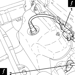
1. Disconnect the electrical connection for the Lambda sensor upstream of the catalytic converter.
| Description | Connector | |
|---|---|---|
| 1 | Lambda sensor on catalyzer | See K017 LAMBDA SENSOR ON CATALYZER |
2. Disconnect the electrical connection for the Lambda sensor downstream of the catalytic converter.
| Description | Connector | |
|---|---|---|
| 2 | Lambda sensor on catalyzer | See K017 LAMBDA SENSOR ON CATALYZER |
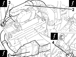
1. Disconnect the intermediate engine wiring coupling.
| Description | Connector | |
|---|---|---|
| 1 | Engine cables/engine services cable coupling | See D029 ENGINE CABLES/ENGINE SERVICES CABLE COUPLING |
2. Connect the electrical connection for the injection control unit.
| Description | Connector | |
|---|---|---|
| 2 | Engine management control unit | See M010 ENGINE MANAGEMENT ECU |
3. Undo the nut and disconnect the earth lead from the injection control unit mount.
| Description | Connector | |
|---|---|---|
| 3 | Injection control unit earth | See C060 INJECTION CONTROL UNIT EARTH |
4. Disconnect the electrical connection for the timing sensor.
| Description | Connector | |
|---|---|---|
| 4 | Timing sensor | See K047 TIMING SENSOR |
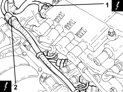
1. Disconnect the electrical connection from the ignition coil module.
| Description | Connector | |
|---|---|---|
| 1 | Ignition coil | See A030 IGNITION COIL |
2. Disconnect the intermediate injector wiring coupling.
| Description | Connector | |
|---|---|---|
| 2 | Injector coupling | See D081 INJECTOR COUPLING |
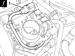
1. Disconnect the electrical connection for the throttle casing.
| Description | Connector | |
|---|---|---|
| 1 | Integrated throttle casing actuator | See N075 INTEGRATED THROTTLE CASING ACTUATOR |
1. Disconnect the electrical connection for the engine coolant temperature sensor.
| Description | Connector | |
|---|---|---|
| 1 | Engine coolant temperature sensor/sender unit | See K036 ENGINE COOLANT TEMPERATURE SENSOR/SENDER UNIT |
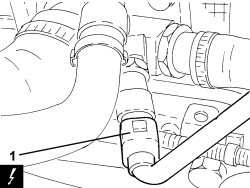
1. Disconnect the electrical connection of the fuel vapour flow enablement solenoid valve.
| Description | Connector | |
|---|---|---|
| 1 | Fuel vapour recovery solenoid valve | See L010 FUEL VAPOUR RECOVERY SOLENOID VALVE |
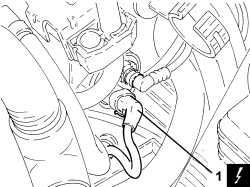
1. Disconnect the electrical connection for the atmospheric pressure sensor.
| Description | Connector | |
|---|---|---|
| 1 | Absolute pressure sensor | See K048 ABSOLUTE PRESSURE SENSOR |
2. Disconnect the electrical connection for the air temperature/pressure sensor.
| Description | Connector | |
|---|---|---|
| 2 | Air pressure - temperature sensor | See K044 AIR PRESSURE - TEMPERATURE SENSOR |
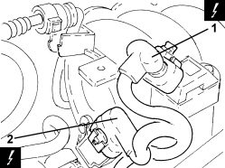
1. Disconnect the electrical connection for the variable valve timing solenoid.
| Description | Connector | |
|---|---|---|
| 1 | Variable valve timing actuator | See N076 PHASE TRANSFORMER ACTUATOR |
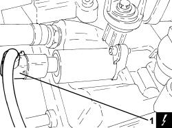
1. Disconnect the electrical connection for the rpm sensor.
| Description | Connector | |
|---|---|---|
| 1 | Rpm sensor | See K046 RPM SENSOR |
2. Disconnect the electrical connection for the minimum engine oil pressure switch.
| Description | Connector | |
|---|---|---|
| 2 | Insufficient engine oil pressure sensor | See K030 INSUFFICIENT ENGINE OIL PRESSURE SENSOR |
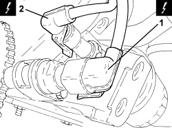
1. Undo the bolt and remove the earth lead from the engine block.
| Description | Connector | |
|---|---|---|
| 1 | Earth on engine | See C040 EARTH ON ENGINE |
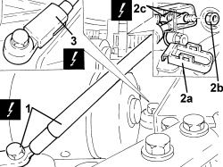
2. Open the protective cover (2a), undo the nut (2b) and disconnect the starter motor electrical connections (2c).
| Description | Connector | |
|---|---|---|
| 2c | Starter motor | See A020 STARTER MOTOR |
3. Disconnect the electrical connection for the detonation sensor.
| Description | Connector | |
|---|---|---|
| 3 | Detonation sensor - 2 | See K050 DETONATION SENSOR |
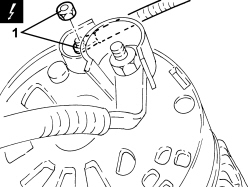
1. Undo the nut and disconnect the alternator earth lead.
| Description | Connector | |
|---|---|---|
| 1 | Alternator | See A010 ALTERNATOR |
- Remove the engine wiring harness.
Refitting
- Place the wiring harness in its seat.
- Connect the earth lead to the alternator.
- Connect the electrical connection for the detonation sensor.
- Connect the electrical connections for the starter motor, tighten the nut and close the protective cover.
- Connect the earth lead to the engine block.
- Connect the electrical connection for the minimum engine oil pressure switch.
- Connect the electrical connection for the rpm sensor.
- Connect the electrical connection for the variable valve timing solenoid.
- Connect the electrical connection for the air temperature/pressure sensor.
- Connect the electrical connection for the atmospheric pressure sensor.
- Connect the electrical connection of the fuel vapour flow enablement solenoid valve.
- Connect the engine coolant temperature sensor electrical connection.
- Connect the electrical connection for the throttle casing.
- Connect the intermediate injector wiring coupling.
- Connect the electrical connection of the ignition coil module.
- Connect the electrical connection for the timing sensor.
- Connect the injection control unit earth lead.
- Connect the electrical connection for the injection control unit.
- Connect the intermediate engine wiring coupling.
- Connect the electrical connection for the Lambda sensor downstream of the catalytic converter.
- Connect the electrical connection for the Lambda sensor upstream of the catalytic converter.
Op. 1048A10 AIR FILTER ASSEMBLY - R.R.
- Connect the negative battery terminal.
- Remove the vehicle from the lift.
Parts & tools for this job For 2000 Fiat Doblò
- PARTEngine gasket setSearch: Fiat Doblò 2000 engine gasket set
- TOOLTorque wrenchSearch: 3/8 inch torque wrench
- TOOLFeeler gauge setSearch: feeler gauge set
Links open Amazon search results in a new tab. As an Amazon Associate I earn from qualifying purchases.