
Power unit with manual gearbox - r + r
- Make
- Fiat
- Model
- Ducato Factory Service Manual
- Year
- 2002–2006
- Section
- Engine and power unit › Power unit with manual gearbox - r + r
POWER UNIT WITH MANUAL GEARBOX - R + R
Removing
- Position the vehicle on a lift.
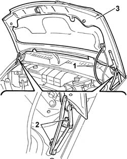
1. Disconnect the windscreen washer jet pipe.
2. Undo the bolts fixing the bonnet lid hinges to the bodyshell.
3. Remove the bonnet lid, with the help of a second mechanic, and place it on a surface taking care over the paintwork.
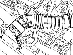
1. Undo the bolts fixing the cold air intake to the upper crossmember.
2. Disconnect the intake hose from the air filter casing.
3. Remove the cold intake and intake hose assembly from the engine compartment.
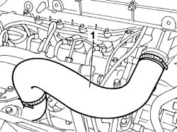
1. Remove the air delivery sleeve to the air-air heat exchanger (intercooler).
- Raise the vehicle.
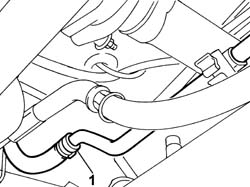
1. Disconnect the oil pipe from the power steering pump and drain the power steering system into a suitable container.
- Reconnect the power steering fluid pipe.
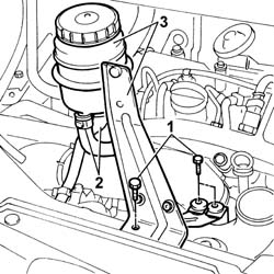
1. Undo the bolts securing the power steering fluid reservoir bracket.
2. Disconnect the fluid pipes from the reservoir.
3. Remove the power assisted steering fluid reservoir complete with bracket.
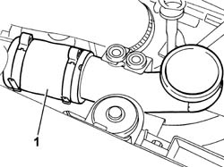
1. Remove the second section of the air delivery sleeve to the air-air heat exchanger (intercooler).
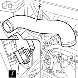
1. Disconnect the right front light cluster electrical connection.
| Description | Connector | |
|---|---|---|
| 1 | Right headlamp | F011 |
2. Disconnect the collars at both ends and remove the air hose from intercooler to intake manifold.
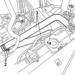
- Arrange a container beneath the engine to recover the engine coolant.
1. Disconnect lower pipe (1a) and upper pipe (1b) from the radiator.
2. Disconnect the pipes from the rigid pipes.
3. Remove the lower and upper radiator pipes.
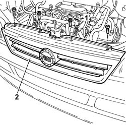
1. Undo the fixing bolts.
2. Remove the front grille.
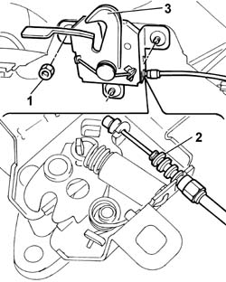
1. Undo the retaining nuts.
2. Disconnect the bonnet lid opening cable.
3. Remove the bonnet lid catch.
- Release the cable from the retaining collars in the engine bay.
Op. 7055B54 UNDER-ENGINE GUARD - R R
Op. 4450B12 FRONT OR REAR WHEELS (TWO) - R+R
Op. 7055B64 LH OR RH REFLECTOR(ONE) ON REAR BUMPERS - R R
- [From both sides]
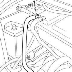
1. Disconnect the recirculation pipe from the engine coolant reservoir.
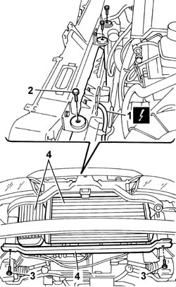
1. Disconnect the fan electrical connections and release the wiring from the retaining collars.
| Description | Connector | |
|---|---|---|
| 1 | Fan motor | N011 |
| Description | Connector | |
|---|---|---|
| 1 | Engine fan motor 2 | N012 |
2. Unscrew the upper radiator/fan unit and intercooler retaining bolts.
- Raise the vehicle and release the lower radiator support beam from the attached wiring.
- Arrange an appropriate hydraulic safety lift beneath the beam.
3. Unscrew the bolts securing the lower beam to the struts.
4. With the aid of a second operator, remove the assembly from the lower part of the engine bay.
- Disconnect the left front light cluster electrical connection.
| Description | Connector | |
|---|---|---|
| Left headlamp | F010 |
1. Unscrew the upper light cluster retaining bolt.
2. Use a suitable tool (2a) to prise light cluster (2b) from its seat, while releasing the pin from the wing.
- Repeat the same operation on the right front light cluster.
| Description | Code | Function | |
|---|---|---|---|
| 2a | Knife | 1.078.077.000 | Prise light cluster out of beam |
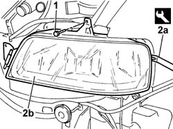
1. Unscrew the nuts and bolts securing the upper beam located inside the light cluster seats.
2. Remove the upper beam from the engine bay complete with front light clusters.
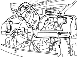
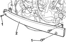
1. Undo the fixing bolts.
2. Remove the crossmember.
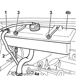
1. Disconnect the band retaining the coolant pipe on the reservoir to the cylinder head.
2. Remove the electrical connection from its seat on the reservoir.
3. Undo the nuts fixing the expansion tank.
4. Disconnect the water pump coolant supply pipe (4a) and remove the expansion tank (4b).
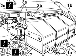
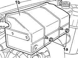
1. Undo the fixing bolts (1a) and remove the protective cover (1b) for the heater plugs control unit.
2. Disconnect the electrical connections for the heater plugs control unit (2a) and (2b) and the control unit positive electrical connection (2c).
| Description | Connector | |
|---|---|---|
| 2a | Heater plugs control unit | M015A |
| Description | Connector | |
|---|---|---|
| 2b | Heater plugs control unit | M015B |
| Description | Connector | |
|---|---|---|
| 2c | Heater plugs control unit | M015C |
3. Undo the fixing nuts (3a) and remove the mounting bracket (3b) complete with heater plugs control unit.
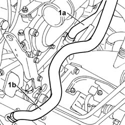
1. Disconnect coolant delivery line (1a) and return line (1b) from the heater.
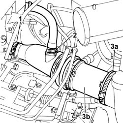
1. Disconnect the band fastening the air supply hose to the turbocharger.
2. Disconnect the vapour recovery pipe from the air supply hose to the turbocharger.
3. Disconnect the band from the air filter casing (3a) and remove the air supply hose to the turbocharger (3b).
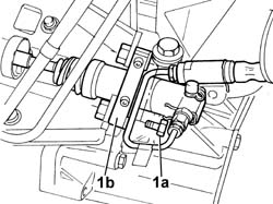
1. Undo bolts (1a) and remove the clutch release cylinder (1b) from its housing.
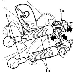
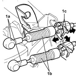
1. Release the two ends (1a), move the two gear selector and engagement flexible cables (1b) out of the slot in the bracket (1c) and place them outside of the work area.
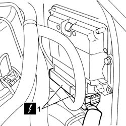
1. Disconnect the engine management unit electrical connections.
| Description | Connector | |
|---|---|---|
| 1 | Engine management control unit | M010A |
| Description | Connector | |
|---|---|---|
| 1 | Engine management control unit | M010B |
1. Disconnect the wiring from the starter motor.
| Description | Connector | |
|---|---|---|
| 1 | Starter motor | A020A |
| Description | Connector | |
|---|---|---|
| 1 | Starter motor | A020B |
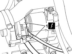
1. Disconnect the electrical connection for the reversing light switch.
| Description | Connector | |
|---|---|---|
| 1 | Reversing lights switch | I020 |
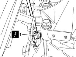
1. Disconnect the electrical connection for the voltage regulator on the alternator.
| Description | Connector | |
|---|---|---|
| 1 | Alternator | A010A |
- Disconnect the remaining electrical wiring from the alternator.
| Description | Connector | |
|---|---|---|
| Alternator | A010B |
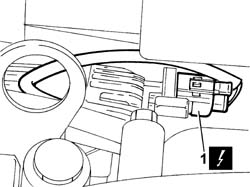
1. Undo the bolts fixing the air filter casing mounting bracket.
2. Undo the bolt fixing the air filter casing to the bracket joined to the windscreen washer fluid reservoir.
3. Remove the air filter casing from the engine compartment.
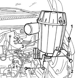
1. Disconnect the electrical connection for the speedometer sensor.
| Description | Connector | |
|---|---|---|
| 1 | Speedometer sensor | K084 |
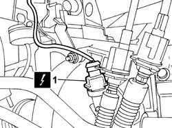
1. Undo the retaining bolt.
2. Remove the engine bay junction unit protective cover.
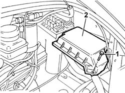
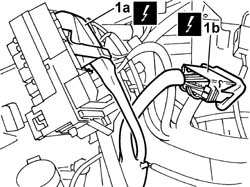
1. Release the junction unit from its seat in the mount and disconnect electrical connections (1a) and (1b).
| Description | Connector | |
|---|---|---|
| 1a | Engine compartment junction unit | B001C |
| Description | Connector | |
|---|---|---|
| 1b | Front/facia coupling | D001A |
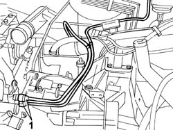
1. Disconnect the brake servo vacuum pipe from the vacuum unit
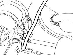
1. Disconnect the two rapid connectors for the fuel supply and return pipes.
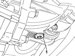
- Have a suitable container for collecting the transmission fluid ready.
1. Undo the plug, using a suitable spanner, and drain the transmission fluid.
| Description | Code | Function | |
|---|---|---|---|
| Spanner | 1.850.182.000 | Wrench for slackening/tightening differential fluid plug |
- Position a hydraulic column lift under the track control arm to work safely.
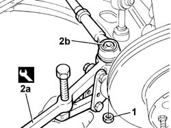
1. Undo the nut fixing the track rod end to the steering knuckle.
2. Extract the track rod end (2b) from the housing in the steering knuckle using the tool (2a).
| Description | Code | Function | |
|---|---|---|---|
| 2a | Head extractor | 1.847.038.000 | Ball joint removal |
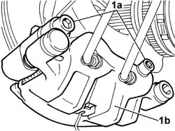
1. Undo the fixing bolts (1a) and remove the brake caliper-bracket assembly (1b) from the brake disc without disconnect the fluid pipes.
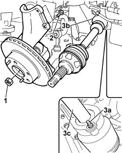
1. Remove the staking and undo the right hub nut.
2. Undo the bolts fixing the steering knuckle to the shock absorber.
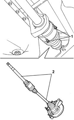
3. Undo the nuts (3a) and remove the right driveshaft (3b) complete with intermediate shaft (3c).
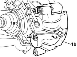
1. Undo the fixing bolts (1a) and remove the left brake caliper-bracket assembly (1b) from the brake disc without disconnect the fluid pipes.
1. Undo the nut fixing the track rod end to the steering knuckle.
2. Extract the track rod end (2b) from the housing in the steering knuckle using the tool (2a).
| Description | Code | Function | |
|---|---|---|---|
| 2a | Head extractor | 1.847.038.000 | Ball joint removal |
3. Undo the bolts fixing the steering knuckle to the shock absorber.
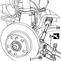
1. Release the inner driveshaft (1a) from the differential and move the right driveshaft (1b) away from the work area.
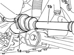
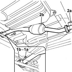
1. Undo the fixing nuts (1a) and separate the ridid middle section of the exhaust pipe from the turbocharger hose flange (1b).
2. Undo the bolts fixing the rear flange (2a) and remove the rigid middle section (2b) of the exhaust pipe.
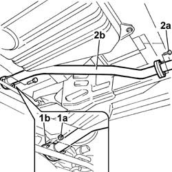
1. Undo the bolt securing the lower reaction rod to the suspension crossmember.
2. Undo the bolt securing the lower reaction rod to the mounting bracket on the gearbox.
3. Remove the lower reaction link.
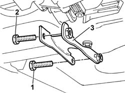
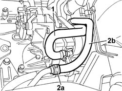
1. Disconnect the return pipe from the power steering pump.
2. Open collar (2a) and disconnect power steering pump delivery pipe (2b) to the steering box.
- Lower the vehicle.
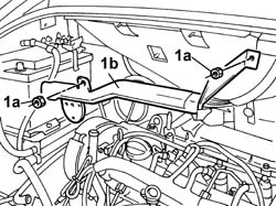
1. Undo retaining bolts (1a) and remove the wiring channel (1b).
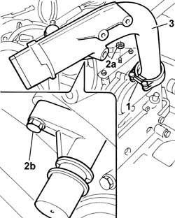
1. Loosen the bolt fixing the collar joining the rigid section of the intake pipe to the turbocharger.
2. Undo the nut (2a) fixing the pipe to the bracket on the cylinder head and the bolt (2b) fixing the connector for the engine oil vapour pipe.
3. Remove the rigid section of the air pipe from the turbocharger.
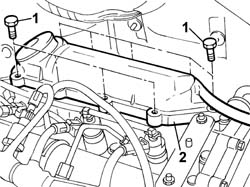
1. Undo the fixing bolts.
2. Remove the engine oil vapour separator.
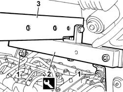
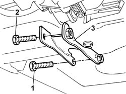
1. Fit the two brackets secured to the cylinder head.
2. Position the tool and secure to the brackets positioned previously.
3. Secure the tool to a hydraulic lift for supporting and removing the power unit.
| Description | Code | Function | |
|---|---|---|---|
| 2 | Crossmember | 1.860.851.003 | Power unit anchorage beam |
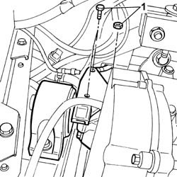
1. Undo the nut and both bolts securing the flexible mount to the timing side rigid power unit mount.
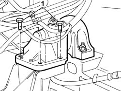
1. Undo the bolts fixing the gearbox side flexible mounting to the rigid support.
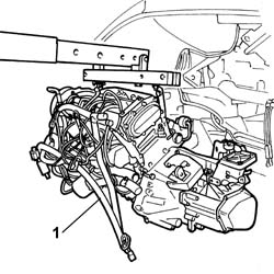
1. Manoeuvre the power unit by tilting and turning. Then adjust the hydraulic lift to move the power unit onto the platform.
Take the greatest care not to damage parts fitted to the vehicle during engine rotation and removal.
Refitting
- Support the power unit by means of a hydraulic lift with chains and position the power unit in its compartment on the vehicle.
Take the greatest care not to damage parts fitted to the vehicle during engine installation.
- Tighten the bolts fixing the gearbox side flexible mounting to the rigid support.
| Value - daNm | Fastening | Component | Ø | |
|---|---|---|---|---|
| (Rigid mount) 5 | Bolt | GEARBOX SIDE RUBBER MOUNT | M10 |
- Tighten the nut and the two bolts fixing the flexible mounting to the timing side rigid power unit support to torque.
| Value - daNm | Fastening | Component | Ø | |
|---|---|---|---|---|
| (Rigid mount on engine) 5 | Bolt | FRONT FLEXIBLE MOUNTING BLOCKS, POWER UNIT | M10 |
| Value - daNm | Fastening | Component | Ø | |
|---|---|---|---|---|
| (Rigid mount on engine) 8 | Nut | FRONT FLEXIBLE MOUNTING BLOCKS, POWER UNIT | M12 |
- Remove the tool and hydraulic lift for supporting and removing the power unit.
| Description | Code | Function | |
|---|---|---|---|
| Crossmember | 1.860.851.003 | Power unit anchorage beam |
- Remove the two brackets secured to the cylinder head.
- Fit the engine oil vapour separator and tighten the retaining bolts.
- Fit the rigid section of the air pipe from the turbocharger.
- Tighten the retaining bolt for the turbocharger union collar to torque.
- Tighten the bolt securing the engine oil vapour recovery pipe connection and nut securing the piping to the cylinder head.
- Positin the wiring channel and secure to the engine bulkhead using retaining bolts.
- Raise the vehicle.
- Connect the delivery and return pipes to the power steering pump.
- Fit the lower reaction rod in the housing and tighten the bolt fixing the suspension crossmember to torque.
- Tighten the nut fixing the reaction rod to the gearbox to torque.
- Fit the rigid middle section of the exhaust pipe and tighten the bolts securing it to the rear section to torque.
| Value - daNm | Fastening | Component | Ø | |
|---|---|---|---|---|
| (Front section flange) 2.6 | Bolts | REAR SILENCER EXHAUST | M8 |
- Tighten the nuts securing the front section of the exhaust pipe to the turbocharger to torque.
| Value - daNm | Fastening | Component | Ø | |
|---|---|---|---|---|
| (Flange on turbocharger) 2.6 | Nut | REAR SILENCER EXHAUST | M8 |
- Fit the inner driveshaft in the housing on the differential for the right driveshaft.
- Tighten the bolts fixing the steering knuckle to the shock absorber to torque.
| Value - daNm | Fastening | Component | Ø | |
|---|---|---|---|---|
| (damper strut) 19 | Bolt | FRONT HUB STRUT | M16 |
- Tighten the nut fixing the ball joint to the steering rod to torque.
| Value - daNm | Fastening | Component | Ø | |
|---|---|---|---|---|
| 6.9 | Nut | ADJUSTABLE LINK BALL JOINTS | M16 |
- Fit the brake caliper - bracket assembly and tighten the bolts fixing the bracket to the left disc to torque.
| Value - daNm | Fastening | Component | Ø | |
|---|---|---|---|---|
| 21 | Bolt | FRONT BRAKE CALIPER BRACKET | M16 |
- Fit the right driveshaft - intermediate driveshaft assembly.
- Tighten the nuts fixing the intermediate driveshaft to the support to torque.
- Tighten the bolts fixing the steering knuckle to the shock absorber to torque.
| Value - daNm | Fastening | Component | Ø | |
|---|---|---|---|---|
| (damper strut) 19 | Bolts | FRONT HUB STRUT |
- Tighten the nut fixing the ball joint to the steering rod to torque.
| Value - daNm | Fastening | Component | Ø | |
|---|---|---|---|---|
| 6.9 | Nut | ADJUSTABLE LINK BALL JOINTS | M16 |
- Fit the brake caliper - bracket assembly and tighten the bolts fixing the bracket to the disc to torque.
| Value - daNm | Fastening | Component | Ø | |
|---|---|---|---|---|
| 21 | Bolt | FRONT BRAKE CALIPER BRACKET | M16 |
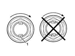
1. Use a hammer and chisel to stake the wheel hub drive shaft retaining nut as shown in the figure.
- The figure below refers to the 15 quintal version.
| Value - daNm | Fastening | Component | Ø | |
|---|---|---|---|---|
| 37 | Nut | FRONT HUBS COMPLETE WITH BEARING | M28 |
- The figure below refers to the 1800 kg version.
| Value - daNm | Fastening | Component | Ø | |
|---|---|---|---|---|
| 42 | Nut | FRONT HUBS COMPLETE WITH BEARING | M33 |
- Connect the fuel delivery line to the pressure pump and the fuel return line to the tank to the quick-release fittings on the return manifold.
- Connect the brake servo vacuum pipe to the vacuum unit
- Connect the electrical connections to the junction unit.
| Description | Connector | |
|---|---|---|
| Engine compartment junction unit | B001C |
| Description | Connector | |
|---|---|---|
| Front/facia coupling | D001A |
- Position the junction unit in its seat on the mount and fit the protective cover.
- Disconnect the electrical connection from the speedometer sensor.
| Description | Connector | |
|---|---|---|
| Speedometer sensor | K084 |
- Fit the air filter casing in the engine compartment.
- Tighten the bolt fixing the air filter casing to the bracket joined to the windscreen washer fluid reservoir.
- Tighten the bolts fixing the air filter casing mounting bracket.
- Connect the voltage regulator electrical connection and the remaining alterantor wiring.
| Description | Connector | |
|---|---|---|
| Alternator | A010A |
| Description | Connector | |
|---|---|---|
| Alternator | A010B |
- Disconnect the electrical connection for the reversing lights switch.
| Description | Connector | |
|---|---|---|
| Reversing lights switch | I020 |
- Connect the wiring to the starter motor.
| Description | Connector | |
|---|---|---|
| Starter motor | A020A |
| Description | Connector | |
|---|---|---|
| Starter motor | A020B |
- Connect the electrical connections for the engine management control unit.
| Description | Connector | |
|---|---|---|
| Engine management control unit | M010A |
| Description | Connector | |
|---|---|---|
| Engine management control unit | M010B |
- Fit both heads of the gear selection and engagement cables and secure them to the bracket.
- Fit the clutch release cylinder and tighten the retaining bolts to the bracket.
- Fit the air supply hose to the turbocharger and connect the two ends to the filter casing and to the actual turbocharger.
- Connect the vapour recovery pipe to the air supply hose to the turbocharger.
- Connect coolant delivery line and return line to the heater.
- Fit the mounting bracket complete with heater plugs control unit.
- Tighten the nuts fixing the control unit to the bodyshell.
- Connect the electrical connections for the heater plugs control unit.
| Description | Connector | |
|---|---|---|
| Heater plugs control unit | M015A |
| Description | Connector | |
|---|---|---|
| Heater plugs control unit | M015B |
| Description | Connector | |
|---|---|---|
| Heater plugs control unit | M015C |
- Fit the protective cover for the heater plugs control unit and tighten the bolts fixing it to the mounting bracket underneath.
- Fit the engine coolant reservoir and tighten the nuts fixing it to the bodyshell.
- Connect the coolant delivery pipe to the pump.
- Fasten the electrical connection in the housing on the tank.
- Connect the band retaining the coolant pipe to the cylinder head.
- Fit the crossmember and tighten the crossmember to torque.
- Fit the upper crossmember in the engine bay complete with front light clusters.
- Tighten the retaining bolts and nuts to torque.
| Value - daNm | Fastening | Component | Ø | |
|---|---|---|---|---|
| 2.9 | Nuts | FRONT WING - HEADLAMP SEAT BEAM | M8 |
- Secure the front light clusters to the crossmember.
- Tighten the upper light cluster retaining bolts to the crossmember.
- Connect the left front light cluster electrical connection.
| Description | Connector | |
|---|---|---|
| Left headlamp | F010 |
- With the aid of a second operator, fit the lower crossmember and radiator assembly from underneath the engine bay.
- Tighten the bolts securing the radiator mounting beam to torque.
| Value - daNm | Fastening | Component | Ø | |
|---|---|---|---|---|
| 8.5 | Bolt | COOLANT RADIATOR SUPPORT BEAM | M12 |
- Secure the wiring to the lower radiator beam and fasten with collars.
- Tighten the upper bolts securing the radiator brackets and fans to the crossmember.
| Value - daNm | Fastening | Component | Ø | |
|---|---|---|---|---|
| 2 | Bolt | ENGINE RADIATOR | M8 |
| Value - daNm | Fastening | Component | Ø | |
|---|---|---|---|---|
| 2 | Bolt | ENGINE RADIATOR FAN/S | M8 |
- Connect the fan electrical connections and release the wiring from the retaining collars.
| Description | Connector | |
|---|---|---|
| Fan motor | N011 |
| Description | Connector | |
|---|---|---|
| Engine fan motor 2 | N012 |
- Connect the recirculation pipe to the engine coolant reservoir.
Op. 7055B64 LH OR RH REFLECTOR(ONE) ON REAR BUMPERS - R R
- [From both sides]
Op. 4450B12 FRONT OR REAR WHEELS (TWO) - R+R
Op. 7055B54 UNDER-ENGINE GUARD - R R
- Connect the bonnet lid opening cable.
- Fit the bonnet catch by screwing in the bolts without tightening.
- Fit the front grille and tighten the bolts.
- Fit the lower and upper radiator pipes and connect them to the ends of the rigid pipes and radiator.
- Fit the air hose from intercooler to intake manifold.
- Connect the right front light cluster electrical connection.
| Description | Connector | |
|---|---|---|
| Right headlamp | F011 |
- Fit the second section of the air delivery sleeve to the air-air heat exchanger (intercooler).
- Fit the power steering fluid reservoir complete with bracket.
- Connect the oil hoses to the reservoir and tighten the power steering fluid reservoir bracket bolts to the beam.
- Fit the air delivery sleeve to the air-air heat exchanger (intercooler).
- Fit the cold intake and intake hose assembly in the engine compartment and tighten the bolts fixing the cold air intake to the upper headlamp holder crossmember.
- Connect the intake hose to the air filter casing.
- Fit the bonnet lid with the help of a second mechanic, taking care not to damage the paintwork.
- Screw in the bolts securing the bonnet lid to the bodyshell without tightening them.
- Connect the windscreen washer jet pipe.
- Adjust the bonnet lid
Op. 0010T10 ENGINE OIL CHECK LEVEL AND TOP UP
Op. 0010T20 COOLANT CHECK DENSITY AND TOP UP IF NECESSARY
Op. 0010T21 COOLANT CHECK DENSITY AND TOP UP IF NECESSARY
Op. 0010T70 POWER ASSISTED STEERING FLUID - REPLACE
Op. 7055B54 UNDER-ENGINE GUARD - R R
Removing
- Position the vehicle on a lift.
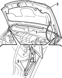
1. Disconnect the windscreen washer jet pipe.
2. Undo the bolts fixing the bonnet lid hinges to the bodyshell.
3. Remove the bonnet lid, with the help of a second mechanic, and place it on a surface taking care over the paintwork.
Op. 7055B54 UNDER-ENGINE GUARD - R R
Op. 4450B12 FRONT OR REAR WHEELS (TWO) - R+R
Op. 7055B64 LH OR RH REFLECTOR(ONE) ON REAR BUMPERS - R R
- [From both sides]
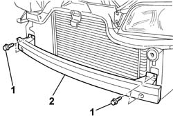
1. Undo the fixing bolts.
2. Remove the crossmember.
- Using a syringe, draw off the power assisted steering fluid from the reservoir.
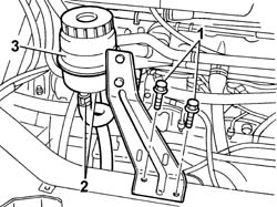
1. Undo the bolts securing the power steering fluid reservoir to the mounting bracket.
2. Disconnect the fluid pipes from the reservoir.
3. Remove the power steering fluid reservoir.
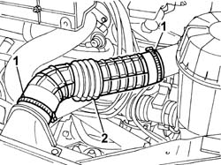
1. Disconnect cold air intake hose from the air filter casing and from the cold air intake.
2. Remove the intake sleeve assembly from the engine bay.
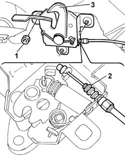
1. Undo the retaining nuts.
2. Disconnect the bonnet lid opening cable.
3. Remove the bonnet lid catch.
- Release the cable from the retaining collars in the engine bay.
- Disconnect the left and right front light cluster electrical connection.
| Description | Connector | |
|---|---|---|
| Left headlamp | F010 |
| Description | Connector | |
|---|---|---|
| Right headlamp | F011 |
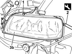
1. Unscrew the upper light cluster retaining bolt.
2. Use a suitable tool (2a) to prise light cluster from its seat, while releasing the pin from the opening in the wing.
3. Undo the nuts fixing the hinges for the left light cluster (3a) and remove the left front light cluster (3b).
- Repeat the same operation on the right front light cluster.
| Description | Code | Function | |
|---|---|---|---|
| 2 | Knife | 1.078.077.000 | Prise light cluster out of beam |
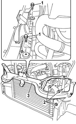
1. Undo the upper retaining bolts for the radiator/fan assembly.
2. Unscrew the nuts and bolts securing the upper beam located inside the light cluster seats.
3. Remove the upper beam from the engine bay complete with front light clusters.
- Arrange a container beneath the engine to recover the engine coolant.
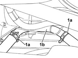
1. Disconnect bands (1a) and disconnect the lower radiator pipe from rigid section (1b).
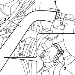
1. Disconnect the uppper radiator pipe.
2. Disconnect the pipes from the thermotat.
3. Remove the upper radiator pipe.
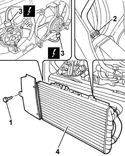
1. Undo the bolt securing the plastic side guard.
2. Disconnect the recirculation pipe to the tank from the radiator.
3. Disconnect the fan electrical connections.
| Description | Connector | |
|---|---|---|
| 3 | Fan motor | N011 |
| Description | Connector | |
|---|---|---|
| 3 | Engine fan motor 2 | N012 |
4. Remove the radiator unit with fans.
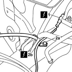
1. Disconnect the right front wheel ABS sensor electrical connection.
| Description | Connector | |
|---|---|---|
| 1 | Right front wheel sensor for ABS | K071 |
2. Undo bolt (2a) and disconnect earth lead (2b) from the body.
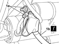
1. Remove the protective caps, unscrew retaining nuts (1a) and disconnect alternator electrical wiring (1b).
| Description | Connector | |
|---|---|---|
| 1b | Alternator | A010A |
| Description | Connector | |
|---|---|---|
| 1b | Alternator | A010B |
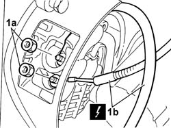
1. Remove the protective boot, undo the fixing nuts (1a) and disconnect the electrical wiring for the starter mtor (1b).
| Description | Connector | |
|---|---|---|
| 1b | Starter motor | A020A |
| Description | Connector | |
|---|---|---|
| 1b | Starter motor | A020B |
- Release the electrical wiring from the bands on the radiator beam and place to one side outside the working area.
- Partly raise the lift.
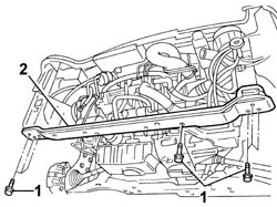
1. Undo the fixing bolts.
2. Remove the radiator supporting crossmember.
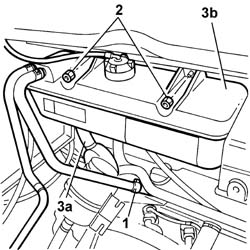
1. Disconnect the band retaining the coolant pipe to the cylinder head.
2. Undo the nuts securing the reservoir to the bodyshell.
3. Disconnect sleeve (3a) from the rigid pipe and remove expansion tank (3b).
1. Undo the fixing bolts (1a) and remove the protective cover (1b) for the heater plugs control unit.
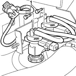
1. Undo the bolts securing both EGR and turbocharging control solenoids to the support beam.
1. Disconnect the electrical connection for the heater plugs control unit.
| Description | Connector | |
|---|---|---|
| 1 | Heater plugs control unit | M015C |
2. Undo the nut securing the glow plug control unit to the bracket.
- Release the wiring from the bands and replace the control unit on the engine.
3. Undo the retaining nuts.
4. Remove the bracket from the engine compartment.
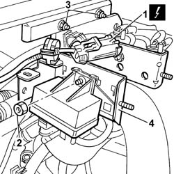
1. Disconnect the single-acting valve from the brake servo.
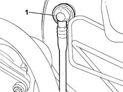
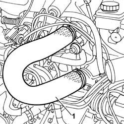
1. Remove the turbocharger intake manifold rigid delivery hose.
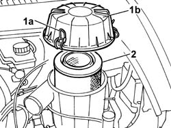
1. Open retaining clips (1a) and remove protective cover (1b) from the filter element.
2. Remove the filter element from the filter casing.
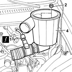
1. Disconnect the electrical connection for the air flow meter.
| Description | Connector | |
|---|---|---|
| 1 | Air flow meter | K041 |
2. Undo the nuts securing the filter casing to the bracket.
3. Disconnect the band securing the air flow meter to the air delivery pipe to the turbo.
4. Remove the air filter casing.
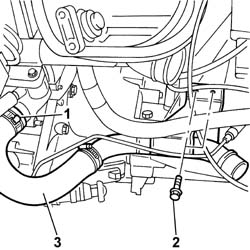
1. Disconnect the lower radiator sleeve from the thermostat.
2. Undo the bolts securing the rigid section of the pipe to the gearbox.
3. Remove the lower radiator pipe.
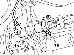
1. Undo bolts (1a) and remove the clutch release cylinder (1b) from its housing.
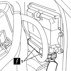
1. Disconnect the engine management unit electrical connections.
| Description | Connector | |
|---|---|---|
| 1 | Engine management control unit | M010A |
| Description | Connector | |
|---|---|---|
| 1 | Engine management control unit | M010B |
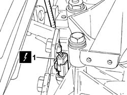
1. Disconnect the electrical connection for the reversing light switch.
| Description | Connector | |
|---|---|---|
| 1 | Reversing lights switch | I020 |
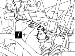
1. Disconnect the electrical connection for the speedometer sensor.
| Description | Connector | |
|---|---|---|
| 1 | Speedometer sensor | K084 |
1. Undo the retaining bolt.
2. Remove the engine bay junction unit protective cover.
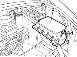
1. Release the junction unit from its seat in the mount and disconnect electrical connections (1a) and (1b).
| Description | Connector | |
|---|---|---|
| 1a | Engine compartment junction unit | B001C |
| Description | Connector | |
|---|---|---|
| 1b | Front/facia coupling | D001A |
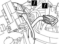
1. Undo bolt (1a) and remove gearbox earth lead (1b) from the body.
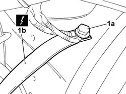
1. Disconnect the fuel pipe from the return manifold by releasing from the retaining bands.
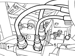
1. Undo connector (1a) and disconnect oil delivery pipe (1b) to the power assisted steering box.
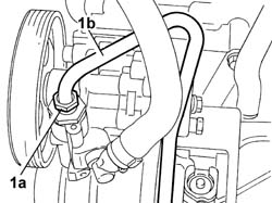
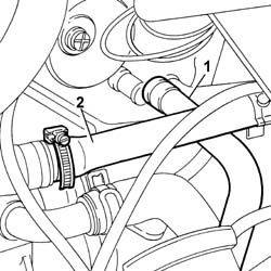
1. Disconnect the engine coolant return pipe from the heater.
2. Disconnect the engine coolant delivery pipe to the supplementary radiator from the rigid exhaust gas recirculation pipe.
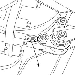
- Have a suitable container for collecting the transmission fluid ready.
1. Undo the plug, using a suitable spanner, and drain the transmission fluid.
| Description | Code | Function | |
|---|---|---|---|
| Spanner | 1.850.182.000 | Wrench for slackening/tightening differential fluid plug |
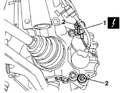
1. Disconnect the electrical connection for the left front brake pad wear sensor.
| Description | Connector | |
|---|---|---|
| 1 | Left brake pad wear sensor (switch) | K020 |
2. Undo the bolts fixing the brake caliper to the bracket and move it aside without disconnecting the oil pipe.
- Position a hydraulic column lift under the track control arm to work safely.
1. Undo the nut fixing the track rod end to the steering knuckle.
2. Extract the track rod end (2b) from the housing in the steering knuckle using the tool (2a).
| Description | Code | Function | |
|---|---|---|---|
| 2a | Head extractor | 1.847.038.000 | Ball joint removal |
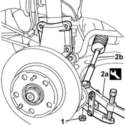
1. Undo the bolts fixing the steering knuckle to the shock absorber.
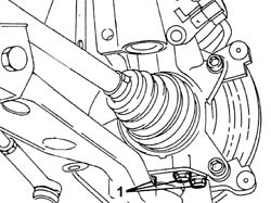
2. Undo the retaining bolt.
3. Remove the left ABS sensor from the housing and place it outside the work area.
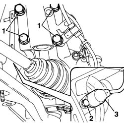
1. Undo the bolts fixing the stub axle to the steering knuckle.
1. Prise up the internal drive shaft (1a) from its seat on the differential, then remove the drive shaft - strut - brake disc assembly (1b).
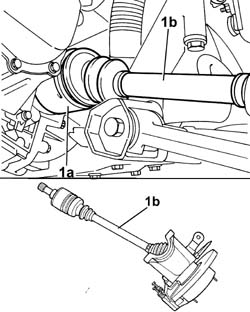
- Position a hydraulic column lift under the track control arm to work safely.
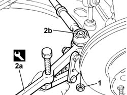
1. Undo the nut fixing the track rod end to the steering knuckle.
2. Extract the track rod end (2b) from the housing in the steering knuckle using the tool (2a).
| Description | Code | Function | |
|---|---|---|---|
| 1a | Head extractor | 1.847.038.000 | Ball joint removal |
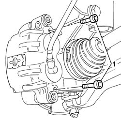
1. Undo the bolts fixing the brake caliper to the bracket and move it aside without disconnecting the oil pipe.
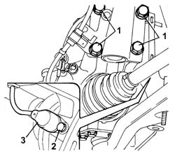
1. Undo the bolts fixing the steering knuckle to the shock absorber.
2. Undo the retaining bolt.
3. Remove the right ABS sensor from the housing and place it outside the work area.
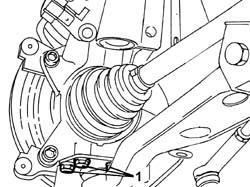
1. Undo the bolts fixing the stub axle to the steering knuckle.
1. Undo the bolts securing the intermediate driveshaft to the mount.
2. Remove the intermediate drive shaft - right drive shaft assembly with strut and brake disc.
1. Release the two ends (1a), move the two gear selector and engagement flexible cables (1b) out of the slot in the bracket (1c) and place them outside of the work area.
1. Undo nuts (1a) and separate the exhaust pipe from the flange (1b) for the turbocharger hose.
2. Undo the bolts securing the rear flange (2a) and remove the exhaust pipe attachment to the engine (2b).
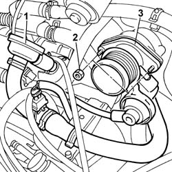
1. Undo the clip and disconnect the oil vapour recovery pipe from the cam cover.
2. Undo the retaining nuts.
3. Remove the throttle body from the intake manifold.
1. Undo the bolt securing the lower reaction rod to the suspension crossmember.
2. Undo the bolt securing the lower reaction rod to the mounting bracket on the gearbox.
3. Remove the lower reaction link.
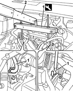
1. Position the tool and secure with hooks to the brackets on the engine.
2. Secure the tool to a hydraulic lift for supporting and removing the power unit.
| Description | Code | Function | |
|---|---|---|---|
| 1 | Crossmember | 1.860.851.003 | Power unit anchorage beam |
- Place a support under the power unit to rest the power unit on later on.
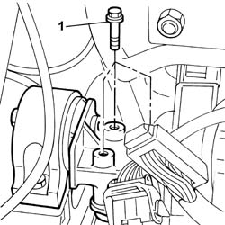
1. Undo the bolts fixing the flexible mounting to the timing side rigid power unit support.
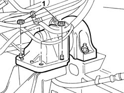
1. Undo the nuts fixing the gearbox side flexible mounting to the rigid support.
1. Manoeuvre the power unit acting on the hydraulic lift and lower it slowly until it is resting on the support.
- Raise the vehicle and extract the support placing it away from the actual vehicle.
Take the greatest care not to damage parts fitted to the vehicle during the removal of the engine.
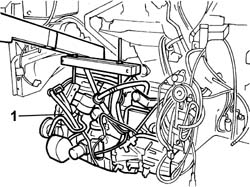
Refitting
- Support the power unit by means of a hydraulic lift with chains and position the power unit in its compartment on the vehicle.
Take the greatest care not to damage parts fitted to the vehicle during engine installation.
- Tighten the nuts fixing the gearbox side flexible mounting to the rigid support.
| Value - daNm | Fastening | Component | Ø | |
|---|---|---|---|---|
| (Rigid mount) 5 | Nuts | GEARBOX SIDE RUBBER MOUNT | M10 |
- Tighten the nut and the two bolts fixing the flexible mounting to the timing side rigid power unit support to torque.
| Value - daNm | Fastening | Component | Ø | |
|---|---|---|---|---|
| (Rigid mount on engine) 5 | Bolt | FRONT FLEXIBLE MOUNTING BLOCKS, POWER UNIT | M10 |
| Value - daNm | Fastening | Component | Ø | |
|---|---|---|---|---|
| (Rigid mount on engine) 8 | Nut | FRONT FLEXIBLE MOUNTING BLOCKS, POWER UNIT | M12 |
- Remove the tool and hydraulic lift for supporting and removing the power unit.
| Description | Code | Function | |
|---|---|---|---|
| Crossmember | 1.860.851.000 | Power unit anchorage beam |
- Fit the throttle body with built-in pneumatic valve and tighten the retaining nuts.
- Fit the lower reaction rod in the housing and tighten the bolt fixing the suspension crossmember to torque.
- Tighten the nut fixing the reaction rod to the gearbox to torque.
- Fit the rigid middle section of the exhaust pipe and tighten the bolts securing it to the rear section to torque.
| Value - daNm | Fastening | Component | Ø | |
|---|---|---|---|---|
| (Front section flange) 2.6 | Bolts | REAR SILENCER EXHAUST | M8 |
- Tighten the nuts securing the front section of the exhaust pipe to the turbocharger to torque.
| Value - daNm | Fastening | Component | Ø | |
|---|---|---|---|---|
| (Flange on turbocharger) 2.6 | Nut | REAR SILENCER EXHAUST | M8 |
- Connect the oil vapour recovery pipe to the cam cover.
- Connect both ends of the gear selection and engagement cables and secure them to the mounting bracket.
- Fit the intermediate drive shaft - right drive shaft assembly with strut and brake disc.
- Tighten the nuts fixing the intermediate driveshaft to the support to torque.
- Tighten the bolts securing the stub axle to the hub to torque.
- Fit the right ABS sensor in its housing and tighten the retaining bolt.
- Tighten the bolts fixing the steering knuckle to the shock absorber to torque.
| Value - daNm | Fastening | Component | Ø | |
|---|---|---|---|---|
| (damper strut) 19 | Bolts | FRONT HUB STRUT |
- Fit the brake caliper - bracket assembly and tighten the bolts fixing the bracket to the left disc to torque.
| Value - daNm | Fastening | Component | Ø | |
|---|---|---|---|---|
| 21 | Bolt | FRONT BRAKE CALIPER BRACKET | M16 |
- Tighten the nut fixing the ball joint to the steering rod to torque.
| Value - daNm | Fastening | Component | Ø | |
|---|---|---|---|---|
| 6.9 | Nut | ADJUSTABLE LINK BALL JOINTS | M16 |
- Fit the left driveshaft assembly and press fit the inner driveshaft in the housing on the left differential.
- Tighten the bolts fixing the stub axle to the left hub to torque.
- Fit the right ABS sensor in its housing and tighten the retaining bolt.
- Tighten the bolts fixing the steering knuckle to the shock absorber to torque.
| Value - daNm | Fastening | Component | Ø | |
|---|---|---|---|---|
| (damper strut) 19 | Bolt | FRONT HUB STRUT | M16 |
- Tighten the nut fixing the ball joint to the steering rod to torque.
| Value - daNm | Fastening | Component | Ø | |
|---|---|---|---|---|
| 6.9 | Nut | ADJUSTABLE LINK BALL JOINTS | M16 |
- Fit the brake caliper - bracket assembly and tighten the bolts fixing the bracket to the left disc to torque.
| Value - daNm | Fastening | Component | Ø | |
|---|---|---|---|---|
| 21 | Bolt | FRONT BRAKE CALIPER BRACKET | M16 |
- Connect the engine coolant return pipe to the heater.
- Connect the engine coolant delivery pipe to the supplementary radiator to the rigid exhaust gas recirculation pipe.
- Connect the fluid supply pipe to the power assisted steering box and tighten the connector.
- Connect the fuel pipes to the return manifold, securing them to the retaining bands.
- Connect the gearbox earth lead to the bodyshell.
- Connect the electrical connections and reposition the junction unit in the casing.
| Description | Connector | |
|---|---|---|
| Engine compartment junction unit | B001C |
| Description | Connector | |
|---|---|---|
| Front/facia coupling | D001A |
- Fit the engine compartment junction unit protective cover and tighten the fixing bolt.
- Connect the electrical connection for the speedometer sensor.
| Description | Connector | |
|---|---|---|
| Speedometer sensor | K084 |
- Connect the electrical connection for the reversing light switch.
| Description | Connector | |
|---|---|---|
| Reversing lights switch | I020 |
- Connect the electrical connections for the engine management control unit.
| Description | Connector | |
|---|---|---|
| Engine management control unit | M010A |
| Description | Connector | |
|---|---|---|
| Engine management control unit | M010B |
- Place the clutch release cylinder in the housing and tighten the fixing bolts.
- Fit the lower radiator pipe, tighten the bolts fixing it to the bellhousing and connect the hose to the thermostat.
- Fit the air filter casing.
- Connect the band securing the air flow meter to the air delivery pipe to the turbo.
- Tighten the nuts fixing the filter casing to the mounting bracket.
- Connect the electrical connection for the air flow meter.
| Description | Connector | |
|---|---|---|
| Air flow meter | K041 |
- Fit the filter element in the filter casing and fit the protective cover securing it using the fastenings.
- Fit the turbocharger intake manifold rigid delivery hose.
- Connect the single-acting valve to the brake servo.
- Fit the junctiton unit and solenoid valve mounting bracket and tighten the fixing nuts.
- Fit the glow plug control unit to the bracket and tighten the retaining nut.
- Connect the electrical connection for the heater plugs control unit.
| Description | Connector | |
|---|---|---|
| Heater plugs control unit | M015C |
- Fit both EGR and turbo control solenoids to the bracket and tighten the retaining bolts.
- Fit the glow plug and solenoid unit control unit protective cover.
- Fit the engine coolant reservoir and connect the coolant hoses.
- Tighten the nuts securing the reservoir to the bodyshell.
- Fit the radiator supporting crossmember and tighten the fixing bolts to torque.
| Value - daNm | Fastening | Component | Ø | |
|---|---|---|---|---|
| 8.5 | Bolt | COOLANT RADIATOR SUPPORT BEAM | M12 |
- Connect the electrical wiring for the starter motor.
| Description | Connector | |
|---|---|---|
| Starter motor | A020A |
| Description | Connector | |
|---|---|---|
| Starter motor | A020B |
- Connect the alternator electrical wiring.
| Description | Connector | |
|---|---|---|
| Alternator | A010A |
| Description | Connector | |
|---|---|---|
| Alternator | A010B |
- Connect the electrical connection for the right front wheel A.B.S. sensor.
| Description | Connector | |
|---|---|---|
| Right front wheel sensor for ABS | K071 |
- Tighten the fixing bolt and connect the earth lead to the bodyshell.
- Fit the radiator assembly complete with fans.
- Connect the electrical connections for the fans.
| Description | Connector | |
|---|---|---|
| Fan motor | N011 |
| Description | Connector | |
|---|---|---|
| Engine fan motor 2 | N012 |
- Tighten the bolt fixing the side plastic shield.
- Fit the upper radiator pipe and connect it to the thermostat and to the radiator.
- Connect the lower radiator hose to the rigid section of the pipe.
- Fit the upper crossmember in the engine bay complete with front light clusters.
- Tighten the retaining bolts and nuts to torque.
| Value - daNm | Fastening | Component | Ø | |
|---|---|---|---|---|
| 2.9 | Nuts | FRONT WING - HEADLAMP SEAT BEAM | M8 |
- Tighten the nuts fixing the light clusters to the headlamp carrier crossmember.
- Connect the left and right front light cluster electrical connection.
| Description | Connector | |
|---|---|---|
| Left headlamp | F010 |
| Description | Connector | |
|---|---|---|
| Right headlamp | F011 |
- Connect the bonnet lid opening cable.
- Fit the bonnet catch by screwing in the nuts without tightening.
- Fit the cold air intake hose and connect it to the air filter casing and to the cold air intake.
- Fit the power assisted steering fluid reservoir.
- Connect the oil hoses to the reservoir and tighten the power steering fluid reservoir bracket bolts to the beam.
- Fit the crossmember and tighten the fixing bolts to torque.
Op. 7055B64 LH OR RH REFLECTOR(ONE) ON REAR BUMPERS - R R
- [From both sides]
Op. 4450B12 FRONT OR REAR WHEELS (TWO) - R+R
- Fit the bonnet lid with the help of a second mechanic, taking care not to damage the paintwork.
- Screw in the bolts securing the bonnet lid to the bodyshell without tightening them.
- Connect the windscreen washer jet pipe.
- Adjust the bonnet lid
Op. 0010T10 ENGINE OIL CHECK LEVEL AND TOP UP
Op. 0010T20 COOLANT CHECK DENSITY AND TOP UP IF NECESSARY
Op. 0010T21 COOLANT CHECK DENSITY AND TOP UP IF NECESSARY
Parts & tools for this job For 2002 Fiat Ducato
- PARTClutch kitSearch: Fiat Ducato 2002 clutch kit
- TOOLClutch alignment toolSearch: clutch alignment tool
- FLUIDGear oilSearch: Fiat Ducato manual gearbox oil
Links open Amazon search results in a new tab. As an Amazon Associate I earn from qualifying purchases.