
Air chamber - r.r.
- Make
- Fiat
- Model
- Grande Punto Factory Service Manual
- Year
- 2005–2012
- Section
- Inlet and exhaust manifolds › Air chamber - r.r.
AIR CHAMBER - R.R.
Removing
- Disconnect the negative battery terminal.
Op. 1048A10 AIR FILTER ASSEMBLY - R.R.
Op. 1056B60 SINGLE FUEL MANIFOLD PIPE, WITH INJECTORS - R.R.
Op. 1056B54 INTAKE AIR PRESSURE/TEMPERATURE SENSOR - R.R.
Op. 1056B44 AIR PRESSURE SENSOR - R.R.
Op. 1056B14 THROTTLE CASE - R + R
1. Connect the electrical connection to the fuel vapour solenoid valve.
| Description | Connector | |
|---|---|---|
| 1 | Fuel vapour recovery solenoid valve | See L010 FUEL VAPOUR RECOVERY SOLENOID VALVE |
2. Loosen the collar and disconnect the vacuum pipe from the brake servo.
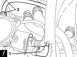
1. Disconnect the intermediate rapid connector for the fuel vapour pipe.
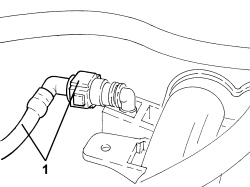
1. Disconnect the electrical connections for the spark plugs.
| Description | Connector | |
|---|---|---|
| 1 | Ignition coil | See A030 IGNITION COIL |
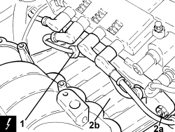
2. Undo fastenings (2a) and remove air capacity chamber (2b).
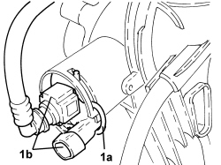
1. Loosen clip (1a) and remove the fuel vapour solenoid (1b) with pipe.
Refitting
- Refit the fuel vapour solenoid with pipe.
- Replace the intake manifold in its housing and secure it by tightening the fastenings to the recommended torque.
| Component | Fastening | dia | Value (daNm) | Validity |
|---|---|---|---|---|
| Intake manifold | Bolt | M8 | 2.3 ÷ 2.8 | 1.2 8v 1.4 8v |
| Component | Fastening | dia | Value (daNm) | Validity |
|---|---|---|---|---|
| Intake manifold | Nut | M8 | 2.3 ÷ 2.8 | 1.2 8v 1.4 8v 1.9 Multijet |
- Connect the electrical connections for the spark plugs.
- Connect the intermediate rapid connector for the fuel vapour pipe.
- Connect the vacuum pipe for the brake servo.
- Connect the electrical connection to the fuel vapour solenoid valve.
Op. 1056B14 THROTTLE CASE - R + R
Op. 1056B44 AIR PRESSURE SENSOR - R.R.
Op. 1056B54 INTAKE AIR PRESSURE/TEMPERATURE SENSOR - R.R.
Op. 1056B60 SINGLE FUEL MANIFOLD PIPE, WITH INJECTORS - R.R.
Op. 1048A10 AIR FILTER ASSEMBLY - R.R.
- Connect the negative battery terminal.
Removing
- Position the vehicle on a lift.
Op. 5530B52 BATTERY SUPPORT/DRIP TRAY - R.R
Op. 1080C82 E.G.R. - VALVE HEAT EXCHANGER ASSEMBLY - CONNECTOR PIPES - R.R.
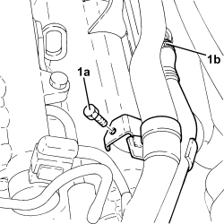
1. Undo the bolts (1a), loosen the band and disconnect the oil vapour recovery pipe between the rigid pipe and the separator (1b), separator side.
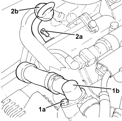
1. Undo the bolt (1a) and disconnect the connector (1b) for the engine oil vapour recovery pipe from the timing cover.
2. Undo the bolt (2a) and remove the engine oil dipstick tube assembly (2b).
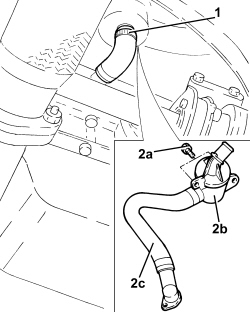
1. Loosen the band and disconnect the oil recovery pipe, separator side.
2. Unscrew the bolts (2a) and remove the engine oil vapour separator (2b) complete with engine oil vapour recovery pipe (2c).
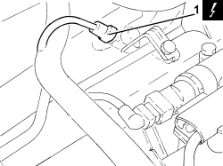
1. Disconnect the electrical connection for the pressure relief sensor.
| Description | Connector | |
|---|---|---|
| 1 | Supercharging sensor | See K082 SUPERCHARGING SENSOR |
- Release the electrical wiring from the bands on the air chamber.
1. Undo the bolts (1a) and remove the air chamber (1b) complete with gasket (1c) and pressure relief sensor.
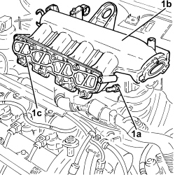
Refitting
- Refit the air chamber complete with gasket and pressure relief sensor back in its housing and secure it tightening the bolts to the recommended torque.
| Component | Fastening | dia | Value (daNm) | Validity |
|---|---|---|---|---|
| Intake manifold | Bolt | M8 | 2.3 ÷ 2.8 | 1.3 Multijet |
- Fasten the electrical wiring using the bands on the air chamber.
- Connect the electrical connection for the pressure relief sensor.
- Replace the engine oil vapour separator wiht engine oil vapour recovery pipe in its seat and secure it with the bolts.
- Connect the oil vapour recovery pipe, separator side and tighten the band.
- Place the engine oil dipstick pipe back in its housing and fasten it with the bolt.
- Connect the connector for the engine oil vapour recovery pipe to the timing cover and tighten the bolt.
Ensure the O-ring is present and correctly positioned.
- Connect the oil vapour recovery pipe between the rigid pipe and the separator, separator side, then tighten the band and the bolts.
Op. 1080C82 E.G.R. - VALVE HEAT EXCHANGER ASSEMBLY - CONNECTOR PIPES - R.R.
Op. 5530B52 BATTERY SUPPORT/DRIP TRAY - R.R
- Remove the vehicle from the lift.
Removing
Op. 1048A32 HOSE FROM AIR FILTER TO INTAKE MANIFOLD - R + R
Op. 1048A10 AIR FILTER ASSEMBLY - R.R.
Op. 1056B60 SINGLE FUEL MANIFOLD PIPE, WITH INJECTORS - R.R.
Op. 5520B10 STARTER MOTOR - R+R
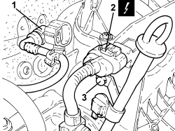
1. Disconnect the intermediate rapid connector for the fuel vapour pipe.
2. Disconnect the electrical connection for the air temperature/pressure sensor.
| Description | Connector | |
|---|---|---|
| 2 | Air pressure - temperature sensor | See K044 AIR PRESSURE - TEMPERATURE SENSOR |
3. Undo the bolt securing the engine oil dipstick tube.
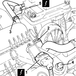
1. Disconnect the electrical connection for the absolute pressure sensor.
| Description | Connector | |
|---|---|---|
| 1 | Absolute pressure sensor | See K048 ABSOLUTE PRESSURE SENSOR |
2. Loosen the band and disconnect the oil vapour pipe from the intake chamber.
3. Loosen the band and disconnect the brake servo vacuum pipe from the intake chamber.
4. Undo the bolt securing the intake manifold to the camshaft housing.
5. Disconnect the electrical connection for the fuel vapour solenoid valve.
| Description | Connector | |
|---|---|---|
| 5 | Fuel vapour recovery solenoid valve | See L010 FUEL VAPOUR RECOVERY SOLENOID VALVE |
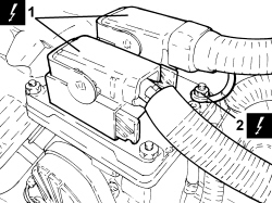
1. Disconnect the electrical connections for the injection-ignition control unit.
| Description | Connector | |
|---|---|---|
| 1 | Engine management control unit | See M010 ENGINE MANAGEMENT ECU |
2. Undo the nut and remove the earth lead for the injection-ignition control unit.
| Description | Connector | |
|---|---|---|
| 2 | Injection control unit earth | See C060 INJECTION CONTROL UNIT EARTH |
1. Disconnect the electrical connection for the slider position sensor.
| Description | Connector | |
|---|---|---|
| 1 |
2. Disconnect the electrical connection for the throttle casing.
| Description | Connector | |
|---|---|---|
| 2 | Integrated throttle casing actuator | See N075 THROTTLE BODY ACTUATOR |
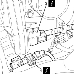
1. Disconnect the electrical connection for the slider solenoid valve.
| Description | Connector | |
|---|---|---|
| 1 | PDA solenoid valve | See L031 PDA SOLENOID VALVE |
2. Open the retaining clips and move the engine wiring duct aside.
3. Undo the lower bolts securing the air chamber to the cylinder head.
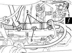
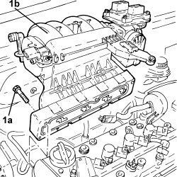
1. Undo the upper bolts (1a) and remove the air chamber assembly (1b).
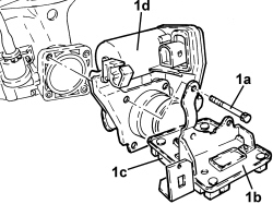
1. Undo the bolts (1a), remove the support (1b) complete with control unit (1c) and throttle casing (1d) complete with gasket.
- Open the clips and disconnect the fuel vapour pipe from the intake chamber.
1. Undo the bolts (1a) and remove the fuel vapour solenoid valve assembly (1b).
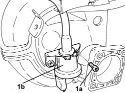
1. Undo the bolt (1a) and remove the absolute pressure sensor (1b) complete with O-ring.
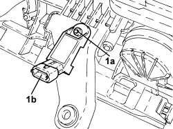
1. Undo the bolt (1a) and remove the air pressure and temperature sensor (1b) complete with O-ring.
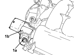
Refitting
- Place the air pressure and temperature sensor back in its housing complete with new O-ring and secure it to the chamber using the bolt.
- Place the air pressure and temperature sensor back in its housing complete with new O-ring and secure it to the chamber using the bolt.
- Place the fuel vapour solenoid valve assembly in position and secure it to the chamber using the bolts.
- Connect the fuel vapour pipe to the chamber and secure it using the clips.
- Place the support complete with control unit, throttle body and new gasket in position and secure it to the chamber using the bolts.
- Place the air chamber assembly in position and tighten the bolts securing it to the cylinder head to the recommended torque.
| Component | Fastening | dia | Value (daNm) | Validity |
|---|---|---|---|---|
| Intake manifold - cylinder head side | Bolt (to be replaced) | M7 | 1.3 ÷ 1.6 | 1.4 16v |
- Refit the engine wiring duct and secure it using the clips.
- Connect the electrical connection for the slider solenoid valve.
- Connect the electrical connection for the throttle casing.
- Connect the electrical connection for the slider position sensor.
- Connect the earth lead for the injection-ignition control unit and secure it using the nut.
- Connect the electrical connections for the injection-ignition control unit.
- Connect the electrical connection for the fuel vapour solenoid valve.
- Tighten the bolt securing the intake chamber to the camshaft housing to the recommended torque.
| Component | Fastening | dia | Value (daNm) | Validity |
|---|---|---|---|---|
| Intake manifold - camshaft housing side | Bolt (to be replaced) | M6 | 0.8 ÷ 1.1 | 1.4 16v |
- Connect the brake servo vacuum pipe to the intake chamber and secure it using the band.
- Connect the oil vapour pipe to the intake chamber and secure with the band.
- Connect the electrical connection for the absolute pressure sensor.
- Tighten the engine oil dipstick tube retaining bolt.
- Connect the electrical connection for the air pressure/temperature sensor.
- Connect the intermediate rapid connector for the fuel vapour pipe to the air chamber.
Op. 5520B10 STARTER MOTOR - R+R
Op. 1056B60 SINGLE FUEL MANIFOLD PIPE, WITH INJECTORS - R.R.
Parts & tools for this job For 2005 Fiat Grande Punto
- PARTExhaust gasketSearch: Fiat Grande Punto 2005 exhaust gasket
- TOOLPenetrating oilSearch: penetrating oil
- TOOLOBD2 scannerSearch: OBD2 scanner
Links open Amazon search results in a new tab. As an Amazon Associate I earn from qualifying purchases.