
Rpm and TDC sensor.
- Make
- Fiat
- Model
- Scudo Factory Service Manual
- Year
- 1996–2006
- Section
- Fuel system (1581 SPI Monomotronic) › Rpm and TDC sensor.
RPM AND TDC SENSOR.
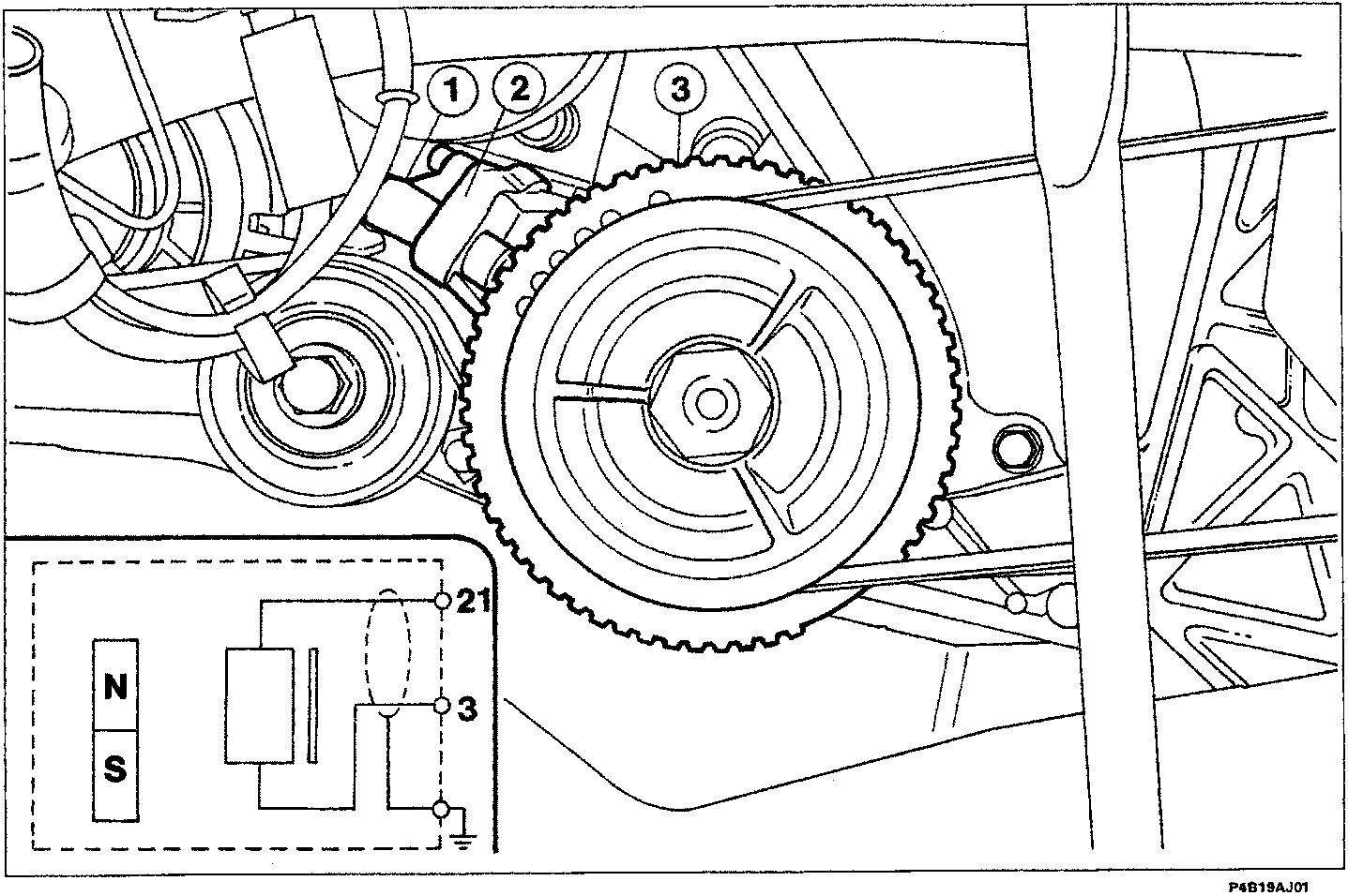
The sensor (1) is fixed on a bracket (2 - fitted to the crankshaft front cover) and is facing a flywheel (3) with 60 - 2 teeth.
It is made up of a hermetically sealed tubular casing which contains a polar core (permanent magnet) and a copper electric winding.
It is connected to the electronic control unit by means of terminals 21 and 3 screened by a copper casing covered in aluminium coated in polyester. This copper casing is connected to the earth point on the inlet manifold.
The operating principle is as follows: the magnetic field in the magnet affects both the winding and the crankshaft pulley teeth.
When the tooth is in front of the sensor, the mangetic flow is maximum, however when there is a gap in front of the sensor the magnetic flow is minimal.
This variation in flow depending on whether there is a tooth (full) or a gap (empty) is sufficient to create a variable electro-motive force (e.m.f.) (positive and negative impulses) in the sensor winding.
The peak voltage produced by this sensor varies from a few Volts at a low speed to several tens of Volts at a high speed.
The variation due the passing of the teeth and the gaps creates a frequency of analogue signals or electro-motive forces which are produced in the sensor every 6°, which are sent to a special circuit (analogue/digital converter) in the control unit and are used for recognizing the engine speed and T.D.C. The missing two teeth on the flywheel (3), produce a reference signal which allows the electronic control unit to recognize T.D.C. for the pair of cylinders 1-4 with an advance of 120°, whilst corresponding to the descent of the fiftieth tooth it recognizes T.D.C. for the pair of cylinders 2-3 and, on the basis of this data, the electronic control unit establishes the correct moment of ignition.
For the engine to run smoothly it is vital that the distance between the sensor and the top of the tooth (gap) is about 1.0 - 0.5 mm (this distance cannot be adjusted).
Parts & tools for this job For 1996 Fiat Scudo
- TOOLOBD2 scannerSearch: OBD2 scanner
- TOOLDigital multimeterSearch: automotive digital multimeter
- TOOLBack-probe test leadsSearch: back probe test leads
Links open Amazon search results in a new tab. As an Amazon Associate I earn from qualifying purchases.