
COMPONENTS TRANSFER for half-finished engine
- Make
- Fiat
- Model
- Stilo Factory Service Manual
- Year
- 2001–2007
- Section
- Engine and power unit › COMPONENTS TRANSFER for half-finished engine
COMPONENTS TRANSFER for half-finished engine
Removing
- 1004D40 engine - position on stand and remove
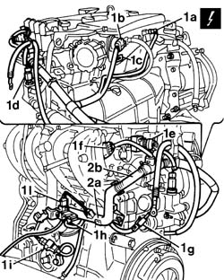
1. Disconnect electrical connections (1a), (1b), (1c), (1d), (1e), (1f), (1g), (1h), (1i) and (1l).
| Name | Connector | |
|---|---|---|
| 1a | Integrated air temperature sensor | K43 |
| Name | Connector | |
|---|---|---|
| 1b | Integrated throttle body actuator | N75 |
| Name | Connector | |
|---|---|---|
| 1d | Engine temperature sender unit | K36 |
| Name | Connector | |
|---|---|---|
| 1e | Ignition coil | A30 |
| Name | Connector | |
|---|---|---|
| 1f | Injector | N70 |
| Name | Connector | |
|---|---|---|
| 1g | Alternator | A10 |
| Name | Connector | |
|---|---|---|
| 1h | Engine oil pressure sensor (switch) | K30 |
| Name | Connector | |
|---|---|---|
| 1i | RPM sensor | K46 |
| Name | Connector | |
|---|---|---|
| 1l | Detonation sensor | K50 |
2. Open the wiring duct (2a) and remove the engine wiring (2b).
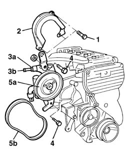
1. Undo the belt plastic guard retaining bolts.
2. Remove the power steering pump belt guard.
3. Unscrew nut (3a) and adjustment screw (3b) to slacken belt tension. Then remove belt (3c).
4. Undo the two bolts fixing the power assisted steering pump.
5. Remove the power assisted steering pump (5a) complete with mounting brackets together with the drive belt (5b).
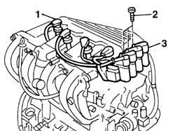
1. Disconnect the supply connections for the spark plugs.
2. Undo the bolts fixing the ignition coils from the mounting bracket.
3. Remove the ignition coils complete with spark plug high tension leads.
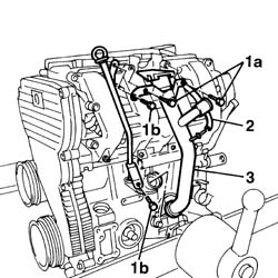
1. Undo the bolts (1a) fixing the oil filler pipe and the bolts (1b) fixing the oil dipstick.
2. Disconnect the oil vapour inlet pipe.
3. Remove the engine oil filler pipe.
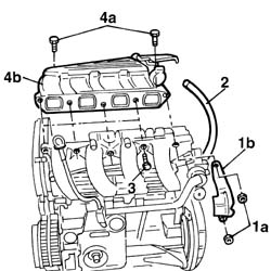
1. Undo the fixing nuts (1a) and remove the protection (1b).
2. Disconnect the flexible engine coolant pipe from the rigid section fixed to the butterfly casing.
3. Undo the bolts fixing the air intake chamber to the inlet manifold.
4. Undo the bolts (4a) fixing the intake chamber to the camshaft housing, then remove the intake chamber (4b).
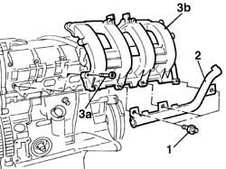
1. Unscrew the retaining nuts.
2. Remove the wiring duct.
3. Undo the fixing bolts (3a) and remove the inlet manifold (3b) together with the oil dipstick.
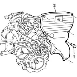
1. Undo the retaining bolts.
2. Remove the timing belt single shield.
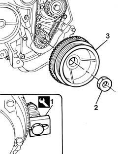
1. Fit the engine flywheel retaining tool.
| Name | Country | |
|---|---|---|
| 1 | Counter-torque | 1.860.846.000 |
2. Undo the nut securing the crankshaft pulley.
3. Remove the crankshaft pulley.
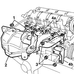
1. Unscrew the retaining nuts.
2. Remove the exhaust manifold heat shield.
3. Unscrew the retaining nuts.
4. Remove the exhaust manifold (4a), together with the mounting bracket (4b) for the power assisted steering pump.
Recover the exhaust manifold seal.
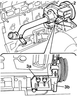
1. Undo the bolts fixing the water pump mounting to the cylinder block/crankcase.
2. Remove the water pump complete with filler pipe.
3. Undo the fixing bolts (3a) and remove the alternator mounting (3b).
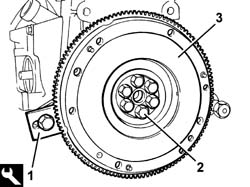
1. Position the flywheel retainer.
| Name | Country | |
|---|---|---|
| 1 | Counter-torque | 1.860.846.000 |
2. Undo the retaining bolts.
3. Remove the engine flywheel together with the flywheel lock positioned previously.
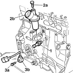
1. Undo and remove the minimum oil pressure warning light sensor.
2. Undo the fixing bolt (2a) and remove the oil vapour separator (2b).
3. Undo the fixing bolt (3a) and remove the detonation sensor (3b).
Refitting
Remove the half complete engine to be replaced from the overhauling stand.
Remove the engine mounting brackets and transfer them to the new half complete engine.
Using a suitable tool, lift the engine and fix it to the rotating stand to fit the missing component.
Fit the detonation sensor on the cylinder block/crankcase.
Position the vapour separator and fix it using the bolt.
Fit the engine oil pressure sender unit/
Position the flywheel retainer.
| Name | Country | |
|---|---|---|
| Counter-torque | 1.860.846.000 |
Fit the engine flywheel and tighten the fixing bolts to torque.
| Fastening | Component | Ø | Value (daNm) | |
|---|---|---|---|---|
| Bolt | FLYWHEEL | M10 | 7.5 - 9.1 |
Fit the water pump complete with rigid pipe.
Tighten the bolts securing the water pump to the crankcase to torque.
| Fastening | Component | Ø | Value (daNm) | |
|---|---|---|---|---|
| Bolt | COOLANT PUMP | M8 | 2.3 ÷ 2.8 |
Fit the alternator mounting bracket and tighten the fixing bolts to torque.
| Fastening | Component | Ø | Value (daNm) | |
|---|---|---|---|---|
| Bolt | ALTERNATOR SUPPORT | M10 | 4.5 ÷ 5.5 |
Fit the exhaust manifold to the cylinder head.
Fit the power assisted steering pump mounting bracket on the exhaust manifold.
Tighten the nuts fixing the exhaust manifold to the cylinder head.
| Fastening | Component | Ø | Value (daNm) | |
|---|---|---|---|---|
| Nut | EXHAUST MANIFOLD/S | M8 | 2.3 ÷ 2.8 |
Fit the exhaust manifold heat shield.
Tighten the nuts fixing the bulkhead.
Fit the crankshaft pulley with its phonic wheel.
Tighten the pulley retaining nut to torque.
| Fastening | Component | Ø | Value (daNm) | |
|---|---|---|---|---|
| Nut | CRANKSHAFT PULLEY | M20 | 18.0 - 20.0 |
Remove the flywheel lock.
| Name | Country | |
|---|---|---|
| Counter-torque | 1.860.846.000 |
Fit the timing belt single shield.
Fit the oil dipstick at the same time as the inlet manifold.
Fit the wiring duct on the inlet manifold.
Tighten the lower bolt fixing the oil dipstick and the nuts fixing the inlet manifold.
| Fastening | Component | Ø | Value (daNm) | |
|---|---|---|---|---|
| Nut | INLET MANIFOLD | M8 | 2.3 ÷ 2.8 |
Fit the air intake casing.
Tighten the bolts and nuts securing the casing to the cylinder head extension.
| Fastening | Component | Ø | Value (daNm) | |
|---|---|---|---|---|
| Bolt | INLET AIR DUCT | M7 | 1.4 ÷ 1.7 |
Tighten the bolts and nuts to the intake manifold.
Fit the shield and fix it using the nuts.
Connect the coolant pipe.
Fit the engine oil filler pipe.
Tighten the fixing bolts and connect the oil vapour inlet pipe.
Fit the ignition coils on the mounting bracket, tightening the bolts to torque.
| Fastening | Component | Ø | Value (daNm) | |
|---|---|---|---|---|
| Bolt | IGNITION COIL/REEL | M6 | 0.8 - 1.0 |
Connect the supply connections for the coils to the spark plugs.
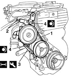
Position the power assisted steering pump complete with supports.
1. Fit the drive belt on the water pump and power assisted steering pump pullies.
2. Acting on the adjustment nut and bolt, tension the power assisted steering pump drive belt.
3. Using a dynamometer, check that the belt tension is correct.
| Name | Country | |
|---|---|---|
| 3 | Torque wrench | 1.895.762.000 |
| Measurement | Value | ||
|---|---|---|---|
| 3 | Power steering pump new belt tension (daN) | 32 - 45 |
4. Tighten the bolts fixing the power assisted steering pump brackets to torque.
| Fastening | Component | Ø | Value (daNm) | |
|---|---|---|---|---|
| 4 | Nut | POWER STEERING PUMP SUPPORT/BRACKET | M10 | 4.5 ÷ 5.5 |
Fit the pump plastic shield.
Position the electrical wiring.
Connect the electrical connection for the detonation sensor.
Connect the electrical connection for the rpm sensor.
Connect the electrical connection to the brake fluid level sensor.
Connect the electrical connection to the alternator.
Connect the electrical connections to the injectors.
Connect the electrical connections to the ignition coils.
Connect the electrical connection to the engine coolant temperature sensor.
Connect the electrical connection to the butterfly position sensor.
Connect the electrical connection to the idle actuator.
Connect the electrical connection to the integratd air temperature sensor.
Position the part of the wiring concerned in the duct.
Parts & tools for this job For 2001 Fiat Stilo
- PARTEngine gasket setSearch: Fiat Stilo 2001 engine gasket set
- TOOLTorque wrenchSearch: 3/8 inch torque wrench
- TOOLFeeler gauge setSearch: feeler gauge set
Links open Amazon search results in a new tab. As an Amazon Associate I earn from qualifying purchases.