
Engine - position on stand and remove
- Make
- Fiat
- Model
- Stilo Factory Service Manual
- Year
- 2001–2007
- Section
- Engine and power unit › Engine - position on stand and remove
Engine - position on stand and remove
Dismantling
Support the engine in order to work on it in safety.
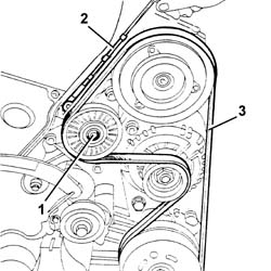
1. Use the automatic belt tensioner to slacken auxiliary drivebelt tension.
2. Remove the auxiliary drivebelt by prising off its drive pulleys.
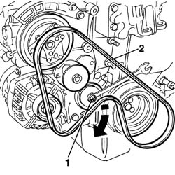
Dismantling
Support the engine in order to work on it in safety.
1. Use the automatic belt tensioner to slacken auxiliary drivebelt tension.
2. Remove the auxiliary drivebelt by prising off its drive pulleys.
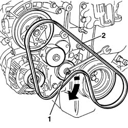
Dismantling
Support the engine in order to work on it in safety.
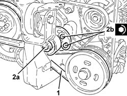
1. Loosen the bolts fixing the air conditioning compressor drive belt tensioner.
2. Slacken the locknut (2a) and undo the micrometric screw (2b) to release the belt tension.
3. Remove the air conditioning compressor drive belt.
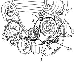
1. Use a spanner on the moving tensioner (1a) and remove the engine components single drive belt (1b).
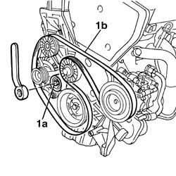
1. Loosen the bolts fixing the alternator - air conditioning compressor drive belt tensioner.
2. Loosen the tension for the alternator - air conditioning compressor drive belt by adjusting the bolt.
3. Remove the alternator - air conditioning compressor drive belt.
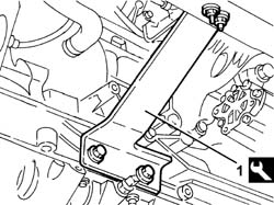
Secure and support the engine using a hydraulic hoist fitted with suitable chains.
Position the engine on the overhauling stand using suitable tools.
1. It is possible to use the tool to support the engine on the overhauling stand.
| Name | Country | |
|---|---|---|
| 1 | Brackets | 1.861.001.039 |
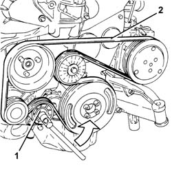
Secure and support the engine using a hydraulic hoist fitted with suitable chains.
1. Use a spanner, in an anti-clockwise direction, on the moving tensioner to loosen the tension of the engine components single drive belt.
2. Remove the single drive belt.
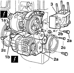
1. Disconnect the electrical connections (1a) from the air conditioner compressor and leads (1b) from the alternator.
| Name | Connector | |
|---|---|---|
| 1a | Air conditioning compressor "on" electromagnet | L20 |
| Name | Connector | |
|---|---|---|
| 1b | Alternator | A10 |
2. Remove mount (2a) with alternator and air conditioner compressor by undoing nuts (2b) and bolts (2c).
3. Remove the engine mount, timing side.
1. Disconnect the electrical connections (1a) from the air conditioner compressor and leads (1b) from the alternator.
| Name | Connector | |
|---|---|---|
| 1a | Air conditioning compressor "on" electromagnet | L20 |
| Name | Connector | |
|---|---|---|
| 1b | Alternator | A10 |
2. Undo the nuts (2a) and the bolts (2b), then remove the mounting complete with air conditioning compressor (2c).
3. Remove the engine mount, timing side.
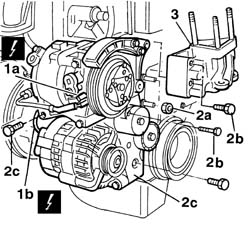
1. Undo the bolt fixing the air conditioning compressor to the inlet manifold.
2. Undo the bolts fixing the rigid engine support to the cylinder block/crankcase.
3. Remove the complete air conditioning compressor, complete with rigid support and belt tensioner.
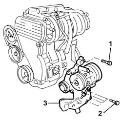
1. Undo the bolts (1a) fixing the bracket to the intermediate driveshaft mounting and the bolts (1b) fixing it to the modular inlet manifold.
2. Remove the reinforcement bracket for the modular inlet manifold.
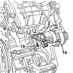
1. Undo the nuts (1a), loosen the band (1b) and remove the pipe (1c) between the supply pipe and the water pump rigid inlet pipe.
2. Undo the bolts (2a) and the screws (2b) and remove the air conditioning compressor (2c).
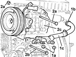
Release the engine from the fastenings.
Secure and support the engine using a hydraulic hoist fitted with suitable chains.
Undo the fixings and remove the engine complete with supporting tools.
Undo the fixings and remove the supporting tools from the engine, then place them down.
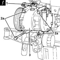
1. Disconnect the electrical connection for the air conditioning compressor.
| Name | Connector | |
|---|---|---|
| 1 | Air conditioning compressor "on" electromagnet | L20 |
2. Undo the bolts (2a) and remove the air conditioning compressor (2b).
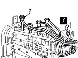
1. Disconnect the electrical connections for the ignition coil.
| Name | Connector | |
|---|---|---|
| 1 | Ignition coil | A30 |
2. Disconnect the HT leads from the spark plug sockets.
3. Remove the ignition coil.
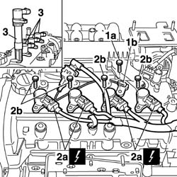
1. Undo the fixing bolt (1a) and extract the timing sensor (1b).
2. Disconnect the electrical connections (2a) for the ignition coils, then undo the bolt (2b) fixing the coils to the cylinder head.
| Name | Connector | |
|---|---|---|
| 2a | Ignition coil | A30 |
3. Remove the ignition coils.
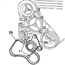
1. Undo the bolts fixing the belt tensioner.
2. Release the belt tension, then remove the belt tensioner (2a), together with the alternator drive belt (2b0.
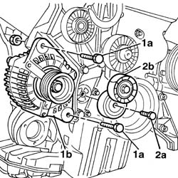
1. Undo the bolts (1a) and remove the alternator (1b).
2. Undo the fixing bolt (2a) and remove the automatic tensioner (2b) for the auxiliary drive belt.
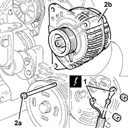
1. Disconnect the electrical connections from the alternator.
| Name | Connector | |
|---|---|---|
| 1 | Alternator | A10 |
2. Undo the bolts (2a) and remove the alternator (2b).
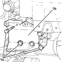
1. Undo the bolts (1a) and remove the air conditioning compresor mounting (1b).
Secure and support the engine for hoisting using a hydraulic hoist fitted with suitable chains.
1. Position the engine bracket on the timing side.
| Name | Country | |
|---|---|---|
| 1 | Bracket | 1.861.001.032 |
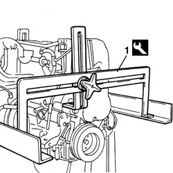
Secure and support the engine for hoisting using a hydraulic hoist fitted with suitable chains.
1. Position the engine bracket on the timing side.
| Name | Country | |
|---|---|---|
| 1 | Bracket | 1.861.001.032 |
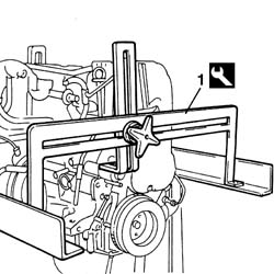
1. Undo the fixing bolts.
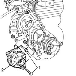
Disconnect the alternator leads.
2. Remove the alternator from the engine.
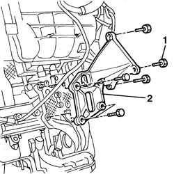
1. Undo the retaining bolts.
2. Remove the reinforcement bracket for the timing tensioner support.
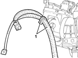
1. Release the electrical wiring from the band on the injection/ignition control unit mounting.
1. Disconnect the electrical connections from the alternator.
| Name | Connector | |
|---|---|---|
| 1 | Alternator | A10 |
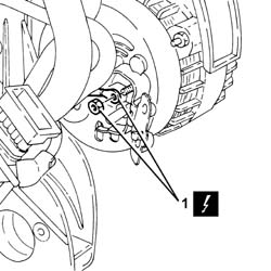
1. Position the engine bracket on the flywheel side.
| Name | Country | |
|---|---|---|
| 1 | Bracket | 1.861.001.034 |
Secure the engine to the overhaul stand using service bolts.
Release the engine from the hoist.
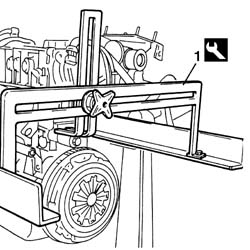
1. Position the engine bracket on the flywheel side.
| Name | Country | |
|---|---|---|
| 1 | Bracket | 1.861.001.034 |
Secure the engine to the overhaul stand using service bolts.
Release the engine from the hoist.
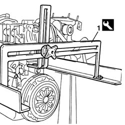
Undo and remove the oil filter.
1. Position the inlet side bracket for supporting the engine whilst overhauling.
| Name | Country | |
|---|---|---|
| 1 | Bracket | 1.861.042.000 |
2. Fix it to the cylinder block/crankcase using the service bolts.
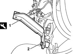
1. Undo the bolts securing the mounting to the crankcase.
2. Undo the bolts fixing the support to the engine oil sump.
3. Remove the intermediate shaft support.
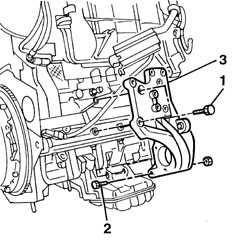
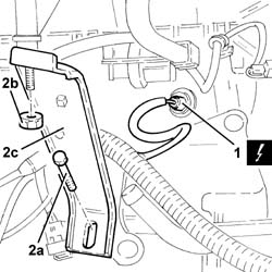
1. Disconnect the electrical connection for the insufficient engine oil pressure sensor.
| Name | Connector | |
|---|---|---|
| 1 | Engine oil pressure sensor (switch) | K30 |
2. Undo the bolt (2a) and the nut (2b) and remove the modular inlet manifold mounting bracket (2c).
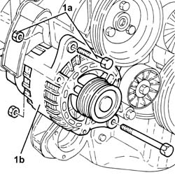
1. Undo the bolts (1a) and remove the alternator (1b).
Reassembling
Secure and support the engine for hoisting using a hydraulic hoist fitted with suitable chains.
Undo the fixing bolts and remove the engine mounting brackets on the rotating stand.
| Name | Country | |
|---|---|---|
| Bracket | 1.861.001.032 |
| Name | Country | |
|---|---|---|
| Bracket | 1.861.001.034 |
Undo the fixings and remove the supporting tools from the engine, then place them down.
Fit the ignition coil
Fit the spark plug HT leads into their seats.
Connect the electrical connection to the ignition coil.
| Name | Connector | |
|---|---|---|
| Ignition coil | A30 |
Fit the timing side engine mount
| Fastening | Component | Ø | Value (daNm) | |
|---|---|---|---|---|
| Bolt | ENGINE MOUNT TIMING SIDE | M10 x 1.25 | 6 |
Fit the mount with alternator and air conditioner compressor.
| Fastening | Component | Ø | Value (daNm) | |
|---|---|---|---|---|
| Bolt | ALTERNATOR SUPPORT | M10 x 1.25 | 5 |
| Fastening | Component | Ø | Value (daNm) | |
|---|---|---|---|---|
| Nut | ALTERNATOR SUPPORT | M10 x 1.25 | 5 |
Connect the alternator leads.
| Name | Connector | |
|---|---|---|
| Alternator | A10 |
Connect the electrical connection to the air conditioner compressor
| Name | Connector | |
|---|---|---|
| Air conditioning compressor "on" electromagnet | L20 |
Fit the auxiliary drivebelt to the drive pulleys, then turn the automatic tensioner and fit the belt.
Remove the hooks and support devices positioned previously.
Reassembling
Secure and support the engine for hoisting using a hydraulic hoist fitted with suitable chains.
Undo the fixing bolts and remove the engine mounting brackets on the rotating stand.
| Name | Country | |
|---|---|---|
| Bracket | 1.861.001.032 |
| Name | Country | |
|---|---|---|
| Bracket | 1.861.001.034 |
Undo the fixings and remove the supporting tools from the engine, then place them down.
Fit the ignition coils in the seats in the cylinder head, then tighten the fixing bolts.
Fit the timing sensor on the cylinder head and tighten the fixing bolt.
Connect the electrical connections to the ignition coils.
| Name | Connector | |
|---|---|---|
| Ignition coil | A30 |
Fit the timing side engine mount
| Fastening | Component | Ø | Value (daNm) | |
|---|---|---|---|---|
| Bolt | ENGINE MOUNT TIMING SIDE | M10 x 1.25 | 6 |
Fit the mount with alternator and air conditioner compressor.
| Fastening | Component | Ø | Value (daNm) | |
|---|---|---|---|---|
| Bolt | ALTERNATOR SUPPORT | M10 x 1.25 | 5 |
| Fastening | Component | Ø | Value (daNm) | |
|---|---|---|---|---|
| Nut | ALTERNATOR SUPPORT | M10 x 1.25 | 5 |
Connect the alternator leads.
| Name | Connector | |
|---|---|---|
| Alternator | A10 |
Connect the electrical connection to the air conditioner compressor
| Name | Connector | |
|---|---|---|
| Air conditioning compressor "on" electromagnet | L20 |
Fit the auxiliary drivebelt to the drive pulleys, then turn the automatic tensioner and fit the belt.
Remove the hooks and support devices positioned previously.
1. Position the exhaust side bracket for supporting the engine whilst overhauling.
| Name | Country | |
|---|---|---|
| 1 | Bracket | 1.861.042.000 |
2. Tighten the bolts.
Fit the engine on the rotating overhaul stand, fixing it with the service bolts.
Remove the engine support chains.
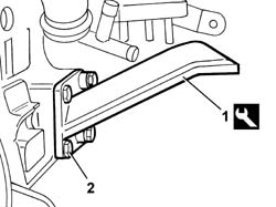
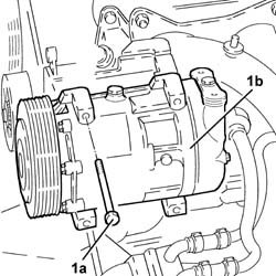
1. Undo the bolts (1a) and remove the air conditioning compressor (1b).
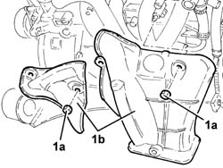
1. Undo the nuts (1a) and remove the heat shield (1b) from the exhaust manifold.
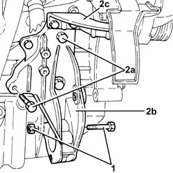
1. Undo the bolt securing the intermediate drive shaft mounting to the crankcase oil sump.
2. Undo the bolts (2a) and remove the intermediate drive shaft mounting (2b) complete with upper alternator bracket (2c).
Reassembling
Position the support chains in the special mounting points, checking that the engine is balanced.
Undo the fixing bolts and remove the engine mounting brackets on the rotating stand.
| Name | Country | |
|---|---|---|
| Bracket | 1.861.042.000 |
Fit the oil filter, tightening it manually.
Fit the alternator in the special housing and tighten the fixing bolts, but not fully.
Connect the alternator leads.
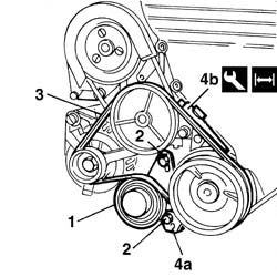
1. Fit the belt tensioner.
2. Tighten the bolts.
3. Fit the alternator drive belt on the pullies.
4. Rotate the tensioning device, working on the hexagonal opening (4a), then check that the belt tension is correct using the tool (4b).
| Name | Country | |
|---|---|---|
| 4b | Torque wrench | 1.895.762.000 |
| Measurement | Value | ||
|---|---|---|---|
| 4b | Check tension (daNm) | 52 - 67 |
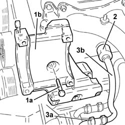
1. Undo the fixing bolts (1a) and remove the air conditioning compressor mounting (1b).
2. Undo the connector and disconnect the rigid section of the heat exchanger coolant outlet pipe.
3. Disconnect the flexible section (3a) of the heat exchanger coolant outlet pipe (3b) and remove it.
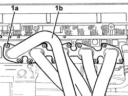
1. Undo the nuts (1a) and remove exhaust manifold (1b) complete with gasket.
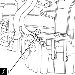
1. Disconnect the electrical connection for the engine oil level sensor.
| Name | Connector | |
|---|---|---|
| 1 | Engine oil level sensor | K32 |
Fit the air conditioning compressor complete with rigid support and belt tensioner.
Tighten the bolts fixing the rigid engine support to the cylinder block/crankcase.
| Fastening | Component | Ø | Value (daNm) | |
|---|---|---|---|---|
| Bolt | ENGINE MOUNT TIMING SIDE | M10 | (Engine side) 6.3 - 7.7 |
| Fastening | Component | Ø | Value (daNm) | |
|---|---|---|---|---|
| Bolt | ENGINE MOUNT TIMING SIDE | M8 | (Engine side) 2.3 ÷ 2.8 |
Tighten the bolts fixing the air conditioning compressor to the inlet manifold to torque.
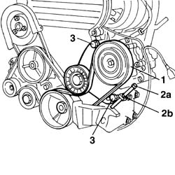
1. Fit the air conditioning compressor drive belt.
2. Acting on the micrometric screw (2a), tension the compressor-air conditioner drive belt, then tighten the locknut (2b).
3. Secure the bolts fixing the air conditioning compressor drive belt tensioner.
Using a dynamometer, check that the belt tension is correct.
| Name | Country | |
|---|---|---|
| Torque wrench | 1.895.762.000 |
| Measurement | Value | ||
|---|---|---|---|
| check tension (daN) | 42 - 55 |
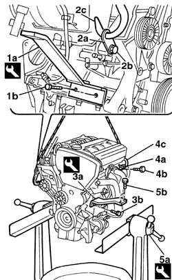
Prepare a hydraulic hoist, complete with metal cables and hooks, for the subsequent securing and positioning of the engine on the rotating stand.
1. Fit the timing side mounting bracket (1a) securing it to the cylinder block/crankcase using the bolts (1b).
| Name | Country | |
|---|---|---|
| 1a | Brackets | 1.861.001.039 |
2. Fit the bracket (2a), securing it to the alternator mounting using the bolt (2a) and fasten the hook (2c) to it.
3. Fit the exhaust side engne mounting bracket (3a), securing it to the cylinder block/crankcase using the bolts (3b).
| Name | Country | |
|---|---|---|
| 3a | Brackets | 1.861.001.039 |
4. Fit the bracket (4a) securing it to the cylinder head using the bolt (4b) and fasten the hook (4c) to it.
5. Lift the engine and position it on the rotating stand (5a) and fix the two engine mounting brackets to it using the fixing bolts (5b).
| Name | Country | |
|---|---|---|
| 5a | Rotating stand | 1.861.000.000 |
When the operation is completed, remove the two brackets fitted previously and place the hydraulic hoist, complete with chains, outside the working area.
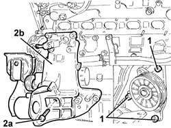
1. Undo the nuts fixing the alternator - air conditioning compressor drive belt tensioner to the timing side rigid engine support.
2. Undo the bolts (2a) and remove the complete timing side rigid engine support (2b).
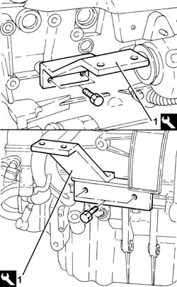
1. Fit the brackets for positioning the engine on the overhauling stand.
| Name | Country | |
|---|---|---|
| 1 | Brackets | 1.861.001.139 |
Tighten the tensioner fixing bolts.
Remove the hooks and support devices positioned previously.
Position two brackets secured to the cylinder head and the alternator upper mounting.
Secure two metal cables to the brackets and tension them with the assistance of a hydraulic hoist.
Undo the bolts fixing the engine mounting brackets to the rotating stand.
| Name | Country | |
|---|---|---|
| Rotating stand | 1.861.000.000 |
Lift the engine and place it onto a stand.
Remove the two exhaust side and timing side engine mounting brackets.
| Name | Country | |
|---|---|---|
| Brackets | 1.861.001.039 |
Remove the brackets positioned previously for attaching the metal cables.
Place the hydraulic hoist outside of the working area.
Fit the heat exchanger coolant outlet pipe.
Tighten the pipe connector to the water pump rigid inlet pipe.
Connect the pipe lower hose to the heat exchanger.
Fit the air conditioning compressor mounting.
Tighten the bolts fixing the air conditioning compressor mounting to torque.
| Fastening | Component | Ø | Value (daNm) | |
|---|---|---|---|---|
| Bolt | Air conditioning compressor support | M10 | 5 |
Fit the air conditioning system compressor.
Tighten the bolts fixing the air conditioning compresor to torque.
| Fastening | Component | Ø | Value (daNm) | |
|---|---|---|---|---|
| Bolt | AIR CONDITIONER ASSEMBLY COMPRESSOR | M8 | 2.5 |
Fit the intermediate shaft bearing support and tighten the bolts fixing it to the cylinder block/crankcase and the engine oil sump to torque.
| Fastening | Component | Ø | Value (daNm) | |
|---|---|---|---|---|
| Bolt | FRONT DRIVE SHAFT BEARING MOUNT | M8 | 2.5 |
| Fastening | Component | Ø | Value (daNm) | |
|---|---|---|---|---|
| Bolt | FRONT DRIVE SHAFT BEARING MOUNT | M10 | 5 |
Fit the timing and various components tensioner mounting bracket.
Tighten the bolts fixing it to the tensioner mounting and to the intermediate driveshaft bearing support.
Fit the auxiliary shaft drive belt moving tensioner and tighten the fixing bolt to torque.
| Fastening | Component | Ø | Value (daNm) | |
|---|---|---|---|---|
| Bolt | AUXILARY BELT MOBILE TENSIONER | M8 | 2.5 |
Fit the alternator and tighten the bolts fixing it to the mounting to torque.
| Fastening | Component | Ø | Value (daNm) | |
|---|---|---|---|---|
| Bolt | AUTOMATIC HEATER CASE | M12 x 1.25 | 7 |
| Fastening | Component | Ø | Value (daNm) | |
|---|---|---|---|---|
| Bolt | AUTOMATIC HEATER CASE | M10 x 1.25 | 5 |
Fit the reinforcement bracket for the modular inlet manifold, tightening the bolts fixing it to the actual manifold and the intermediate driveshaft support.
Fit the auxiliary shaft drive belt and, using a spanner on the moving tensioner, tension the engine components drive belt.
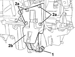
1. Undo the bolt securing the intermediate driveshaft bearing support to the crankcase sump.
2. Undo the bolts (2a) and remove the intermediate driveshaft bearing support (2b).
1. Position the engine on the overhauling stand using the hydraulic lift.
Fasten the mounting brackets to the overhaul stand.
Release the engine from the hydraulic lift fastenings.
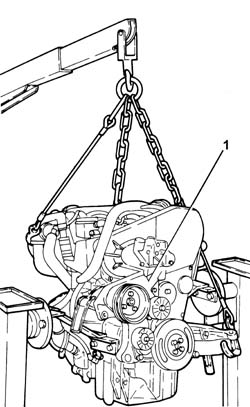
Undo the fixings and remove the complete engine oil dipstick.
1. Fit the tool for positioning the engine on the overhauling stand.
| Name | Country | |
|---|---|---|
| 1 | Brackets | 1.861.001.039 |
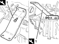
Secure and support the engine using a hydraulic hoist fitted with suitable chains.
Undo the fixings and remove the engine complete with mounting brackets.
Remove the brackets for positioning the engine on the overhauling stand.
| Name | Country | |
|---|---|---|
| Brackets | 1.861.001.139 |
Connect the electrical connection to the engine oil level sensor.
1. Refit intermediate drive shaft (1a) complete with upper alternator mount bracket (1b) and secure it by tightening bolts (1c) to the specified torque.
| Fastening | Component | Ø | Value (daNm) | |
|---|---|---|---|---|
| 1c |
2. Tighten the bolt securing the intermediate drive shaft mounting to the oil sump to the recommended torque.
| Fastening | Component | Ø | Value (daNm) | |
|---|---|---|---|---|
| 2 |
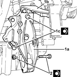
Position the engine on the overhauling stand using a hydraulic hoist fitted with suitable chains.
REMOVAL FROM THE STAND
Remove the engine from the overhauling stand using a hydraulic hoist fitted with suitable chains.
Remove the tool for positioning the engine on the overhauling stand.
| Name | Country | |
|---|---|---|
| Brackets | 1.861.001.039 |
Place the engine oil dipstick back in its housing and fix it using the fastenings.
| Fastening | Component | Ø | Value (daNm) | |
|---|---|---|---|---|
| OIL LEVEL DIPSTICK PIPE | 0.8 - 1.2 |
1. Refit the intermediate driveshaft bearing support (1a) in its seating and tighten the bolts (1b) to the recommended torque.
| Fastening | Component | Ø | Value (daNm) | |
|---|---|---|---|---|
| 1b | Bolt | FRONT DRIVE SHAFT BEARING MOUNT | M10 | (Engine block side) 4.6 ÷ 6.6 |
2. Tighten the bolt fixing the intermediate driveshaft bearing support to the crankcase sump.
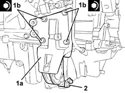
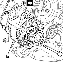
1. Place the alternator (1a) back in its housing and fix it tightening the bolts (1b) to the recommended torque.
| Fastening | Component | Ø | Value (daNm) | |
|---|---|---|---|---|
| 1b |
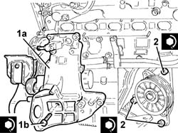
1. Place the complete timing side rigid engine support (1a) back in its housing and secure it tightening the bolts (1b) to the recommended torque.
| Fastening | Component | Ø | Value (daNm) | |
|---|---|---|---|---|
| 1b | Bolt | ENGINE MOUNT TIMING SIDE | M10 | (Engine block side) 4.6 ÷ 6.6 |
2. Tighten the bolts fixing the alternator - air conditioning compressor drive belt tensioner to the timing side rigid engine support.
| Fastening | Component | Ø | Value (daNm) | |
|---|---|---|---|---|
| 2 | Bolt | AUXILARY BELT MOBILE TENSIONER | M8 | (Timing side rigid engine mount side) 2.3 ÷ 3.3 |
Connect the electrical connection to the alternator.
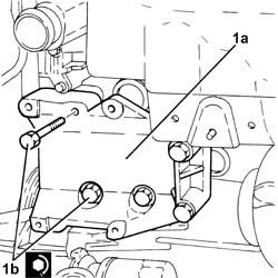
1. Place the air conditioning compressor mounting (1a) back in its housing and fix it tightening the bolts (1b) to the recommended torque.
| Fastening | Component | Ø | Value (daNm) | |
|---|---|---|---|---|
| 1b |
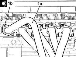
1. Place the exhaust manifold (1a), complete with gasket, back in its housing and fix it tightening the nuts (1b) to the recommended torque.
| Fastening | Component | Ø | Value (daNm) | |
|---|---|---|---|---|
| 1b | Nut | EXHAUST MANIFOLD/S | M8 | (Cylinder head side) 2.3 ÷ 3.3 |
1. Place the air conditioning compressor (1a) back in its housing and secure it tightening the bolts (1b) to the recommended torque.
| Fastening | Component | Ø | Value (daNm) | |
|---|---|---|---|---|
| 1b |
2. Connect the electrical connection to the air conditioner compressor.
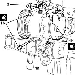
Refit the exhaust manifold heat shield protection and secure it with the nuts.
Place the power assisted steering pump, complete with pipes and electrical wiring, back in its housing.
Refit in its seating the module inlet manifold mounting bracket and fix it with the bolt and nut.
Connect the electrical connection to the engine oil pressure warning sensor.
Fix the electrical wiring to the band on the injection/ignition control unit mounting.
1. Place the alternator (1a) back in its housing and fix it tightening the bolts (1b) to the recommended torque.
| Fastening | Component | Ø | Value (daNm) | |
|---|---|---|---|---|
| 1b | Bolt | ALTERNATOR ASSEMBLY | M10 | 4.6 - 6.6 |
| Fastening | Component | Ø | Value (daNm) | |
|---|---|---|---|---|
| Bolt | ALTERNATOR ASSEMBLY | M12 | 6.4 - 9.3 |
2. Connect the electrical connections to the alternator.
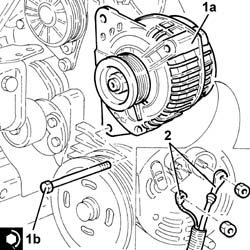
Fit the single engine component belt by adjusting the moving tensioner using a wrench.
Release the engine from the hydraulic lift fastenings.
1. Place the air conditioning compressor (1a) back in its housing and fix it tightening the screws (1b) and the bolts (1c) to the recommended torque.
| Fastening | Component | Ø | Value (daNm) | |
|---|---|---|---|---|
| 1b | Bolt | AIR CONDITIONER ASSEMBLY COMPRESSOR | M8 | (Mount side) 2.3 ÷ 3.3 |
| Fastening | Component | Ø | Value (daNm) | |
|---|---|---|---|---|
| 1c | Bolt | AIR CONDITIONER ASSEMBLY COMPRESSOR | M8 | (Mount side) 2.3 ÷ 3.3 |
2. Place the pipe (2a) from the supply pipe to the water pump rigid inlet pipe back in its housing and secure it using the nuts (2b).
| Fastening | Component | Ø | Value (daNm) | |
|---|---|---|---|---|
| 2b | Nut | COOLANT PUMP RIGID INLET PIPE | 0.8 - 1.2 |
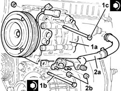
1. Fit the alternator - air conditioning compressor drive belt.
2. Tension the alternator - air conditioning compressor drive belt using the special screw.
Using the C. TRONIC G2 105.5 or similar equipment, check that the tension of the alternator-air compressor conditioner drive belt is within the specified limits.
| Measurement | Value | ||
|---|---|---|---|
| Diameter of hydraulic tappet seats (mm) | 33.000 - 33.025 |
If the tension figure does not correspond to the recommended values, regulate the adjustment screw.
3. Tighten the bolt fixing the alternator - air conditioning drive belt tensioner pulley.
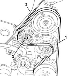
1. Fit the power assisted steering pump drive belt.
2. Tension the power assisted steering pump drive belt using a polygonal spanner on the tensioner screw (2a), then tighten the bolts (2b) to the recommended torque.
| Fastening | Component | Ø | Value (daNm) | |
|---|---|---|---|---|
| 2b | Bolt | POWER ASSISTED STEERING PUMP BELT MOVING TENSIONER | M8 | (Timing side rigid power unit mount side) 2.3 ÷ 3.3 |
Using the tool, check that the power assisted steering pump belt tension is within the recommended limits.
| Name | Country | |
|---|---|---|
| Torque wrench | 1.895.762.000 |
| Measurement | Value | ||
|---|---|---|---|
| Tensioning (daN) | 45 - 62 |
If the tension figure does not correspond to the recommended values, repeat the operations described above.
Parts & tools for this job For 2001 Fiat Stilo
- PARTEngine gasket setSearch: Fiat Stilo 2001 engine gasket set
- TOOLTorque wrenchSearch: 3/8 inch torque wrench
- TOOLFeeler gauge setSearch: feeler gauge set
Links open Amazon search results in a new tab. As an Amazon Associate I earn from qualifying purchases.