
Air bag system
- Make
- Fiat
- Model
- Ulysse Factory Service Manual
- Year
- 2002–2010
- Section
- Instrument/gauge electrical circuits › Air bag system
AIR BAG SYSTEM
INTRODUCTION
The airbag system fitted to the car is activated following moderate to severe front or side impact to protect the occupants.
The system is equipped with a smart system capable of activating the front activation devices, either partly or completely, depending on the seriousness of the accident, whilst the Side Bags and Window Bags guarantee protection for the chest and the head, respectively.
It is NECESSARY for occupants to wear their seat belts correctly to ensure the air bags work to maximum effectiveness.
The side protection system (Window Bags and Side Bags) do not have a dual stage (smart) system which is only fitted on the two front modules
Air bag system components are designed to work on a specific vehicle. They therefore CANNOT be tampered with, adapted or installed on other types of vehicle. Any attempt to reuse, adapt or install on another type of vehicle may cause severe or fatal injury to car occupants during normal use or in the case of impact.
The car must be handed over to the customer with the passenger airbag deactivation switch in ON position and control panel warning lights off.
For safety reasons, NO continuity checks can be carried out on the wiring.
GRAVE DANGER! The front airbag module MUST be deactivated using the special switch if a child seat is fitted to the front passenger seat.
COMPOSITION
The system consists of the following devices:
- one Air Bag Node (NAB);
- twin (driver and passenger) front air bags with dual stage activation,
- two side air bags (side bags) on the front seats;
- two seat belt sensors for the front seats;
- two seat position sensors (left and right);
- passenger air bag manual disabling switch,
- two electronically activated front seat belts with pretensioners with load restricter:
- a front module for protecting the driver´s knees;
- two side protection window modules;
- two side impact sensors fitted on the side pillars (one for the right side and one for the left side);
- two electronically activated rear seat belts with pretensioners with load restricter:
The following indications show the system is working properly:
- fault warning light (red) in the milometer warning lights node;
- passenger air bag disabled warning light in the milometer warning lights node;
- tester input, which converses on the K line, to check operation using an EXAMINER.
AIR BAG Node
The Air Bag Node (NAB) located on the underbody is illustrated in the diagram.
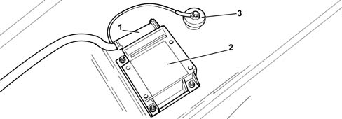
- 1 Connector
- 2 NAB
- 3 Earth
Specifications
The NAB Pin Out is illustrated below.
| Pin | Description |
|---|---|
| 1 | driver cushion + N°2 |
| 2 | driver cushion - N°2 |
| 3 | passenger cushion + N°2 |
| 4 | passenger cushion - N°2 |
| 5 | Satellite 1 right + |
| 6 | chest and right curtain + |
| 7 | chest and right curtain - |
| 8 | Satellite 1 right - |
| 9 | Satellite 1 left - |
| 10 | chest and left curtain + |
| 11 | chest and left curtain - |
| 12 | Satellite 1 left + |
| 13 | Left pretensioner + |
| 14 | Left pretensioner - |
| 15 | |
| 16 | Knee cushion + |
| 17 | Knee cushion - |
| 18 | passenger cushion + N°1 |
| 19 | passenger cushion - N°1 |
| 20 | driver´s cushion + N°1 |
| 21 | driver´s cushion - N°1 |
| 22 | Right pretensioner + |
| 23 | Right pretensioner - |
| 24 | |
| 25 | |
| 26 | SHORT CIRCUIT |
| 27 | |
| 28 | SHORT CIRCUIT |
| 29 | |
| 30 | VAN DATA + |
| 31 | SHORT CIRCUIT |
| 32 | |
| 33 | VAN DATA - |
| 34 | EARTH |
| 35 | SHORT CIRCUIT |
| 36 | |
| 37 | + VAN |
| 38 | SHORT CIRCUIT |
| 39 | |
| 40 | |
| 41 | SHORT CIRCUIT |
| 42 | |
| 43 | SHORT CIRCUIT |
| 44 | |
| 45 | SHORT CIRCUIT |
| 46 | |
| 47 | Ignition key at "MAR" (+15) |
| 48 | |
| 49 | Contact board inhibition + |
| 50 | Contact board inhibition return |
The electronic node is located under the centre tunnel and is designed to electronically manage the entire system checking all the components in order to activate either just the pretensioners or the pretensioners and the air bag modules depending on the nature and the severity of the impact. The node is rigidly secured to the body beneath the central car consule near the centre of gravity. This location allows interior deceleration sensors to detect car deceleration with accuracy.
The NAB should always be fitted with the arrow, stamped on the adhesive plate, facing the direction of travel of the vehicle. Always check that there are no foreign bodies between the Air Bag Node and the bodyshell and tighten the fixing bolts to the recommended torque.
The Air Bag Node contains deceleration sensors including one electromechanical safety sensor that activates an activation enablement function independently of the electronic sensor.
If the car deceleration level detected by the electronic sensor and processed by the ECU in terms of impact severity, exceeds the severity level set for the device deactivation control, the system allows the command to be sent only if the safety sensor is closed at the same moment.
The following functions are present to ensure the system is correctly managed:
- energy accumulation: the presence of a condenser, which acts as an energy reserve, ensures the full operation of the front primers to guarantee operation if there is a break in the power supply at the time of the impact
- fault memory: with the key ON, the Air Bag Node continuously monitors circuit operation (including energy reserve circuits) during normal vehicle operation and impacts. It also diagnoses all electrical parts of the system and indicates the presence of faults by turning on an airbag system fault warning light on the instrument panel and saving the fault code.
- crash memory: records information on crash events that trigger activation of the pretensioners and front or side modules.
The Air Bag Node interfaces with the VAN Car 1 network which is connected with the body computer node as illustrated below
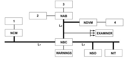
- 1 Webasto fuel pump disabling
- 2 Air Bag modules
- 3 Passenger Air Bag disabling key
- 4 Fuel injection pump disabling
- L1 - CAN
- L2 - VAN CAR 1 network
- L3 - VAN Comfort
In the case of an impact, the Air Bag Node sends the activation command to the modules involved; the activation signal, which travels on the VAN Car 1 network, reaches the Engine Compartment Junction Unit Node (NDVM) which inhibits the injection pump (4 in the diagram). The signal is forwarded by the NBC to the CAN and to the VAN Confort network:
- The NBC controls the release of the door locks and activates the hazard warning lights (warnings in the diagram)
- On the VAN Confort network, the NIT (if fitted) informs of the activation of the Air Bags by sending an emergency call. (see note)
- The signal is received on the CAN by the NCM which inhibits the fuel pump (1 in the diagram) for the Webasto additional heater (if fitted)
An automatic call is always followed by a confirmation phonecall from the service centre to check the circumstances of the call. This ensures a type of "filtering" and prevents the emergency services being sent unnecessarily guaranteeing that they are available if a serious accident should take place.
Operation
The activation of the protective devices is subject to the information acquired directly from the actual node and via the vehicle network. In the case of a frontal impact, the system receives and filters the information, processes it, confirms it and determines the nature of the impact. In particular, the system makes use of information relating to whether or not the front seat belts are fastened (for the activation of the front air bags), the position of the front seats (for the activation of the front air bags) and the speed of the vehicle in order to lower the activation levels for the pyrotechnic components.
The front air bags, in turn, feature dual stage activation by means of a twin pyrotechnic charge
The dual stage system makes it possible to activate the front bags using different inflation methods: witht maximum inflation energy or with minimum inflation energy. This energy is controlled by using two charges for each air bag which are primed in sequence in accordance with a logic processed by the actual NAB.
Side impact
Similarly, when side impact occurs, the system is able to recognise direction and intensity and thus activate the airbags present on the side affected by impact. To provide total cover against side impacts, two satellite sensors located in the centre pillars (one on each side) are used. When a side impact takes place, the satellite sensors detect the impact signal directly along the transverse axis of the vehicle and send it to the Node. This signal, processed by the microprocessor, makes it possible to detect the seriousness of the side impact and, as a result, to decide whether to activate the side air bag on the side involved.
Vehicle roll over
The Air Bag Node is capable of determining the angular speed (through a dedicated sensor) checking whether the vehicle has turned over. In this situation, the system activates both Window Bags, the Side Bags and the pretensioners fitted.
the activation of the air bag modules is independent of the activation of the pretensioners.
System self-diagnosis
The Air Bag Node carries out continuous self-diagnosis of system operation. More specifically:
- it detects and stores faults;
- it indicates the source of these fault by turning on an instrument panel warning light.
- it recognises the various components and the fault type;
Faults stored in the control unit may be deleted only after the fault has been repaired by means of the EXAMINER device.
Driver´s AIR BAG module
The driver´s air bag module is illustrated below
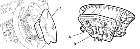
- 1 Driver´s airbag module
- A - Green connector
- B - Blue connector
Composition
The driver´s air bag is a device designed to protect the driver in the case of medium-serious frontal impacts by placing a bag between the occupant and the steering wheel.
The module comprises:
- a 60 litre bag, made out of silicon polyammide cloth designed to minimse skin abrasions in the case of contact and folded in such a way as to ensure that inflation is gradual and not directed toward the driver;
- a hybrid pressurized gas generator
- a containment case.
A warning plate on the base of the gas generator shows handling instructions
Operation
Bag inflation is determined by a gas generator that offers two intervention stages that can be activated separately according to impact severity.
The two pyrotechnic charges explode in sequence: the difference in time between the activation of the first and second charges determines the inflation energy of the bag.
Depending on the extent of the impact, whether or not the seat belts are fastened and the distance of the seat from the steering wheel, the system controls the activation of the air bags in accordance with the different operating modes.
Passenger AIR BAG module
The following figure shows an assembly view
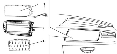
- 1 Connector
- 3 Bag support
- 4 Panel support
- 2 Inflatable bag
Composition
The module comprises:
- a metal mount containing the hybrid gas generator and bag;
- a cover that tears at preset points when activated to allow the bag to expand correctly;
- a 100 litre fabric bag designed to keep skin abrasions to a minimum in case of contact which is specially folded;
- a gas generator comprising a hybrid pressurized gas container
- a connection point to the electrical system;
A warning plate on the bag cover shows handling instructions
The passenger air bag flap is located at the top of the dashboard in a position so that the bag comes out towards the passenger tearing the flap built into the dashboard at pre-set points.
The passenger air bag module activation principle is the same as that described for the driver´s air bag module.
Passenger Air Bag disabling switch with key
View showing location on car
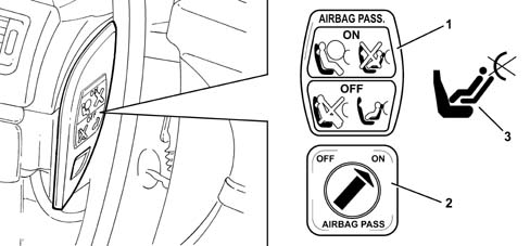
- 1 Passenger air bag on/off position plate
- 2 key-operated switch
- 3 Passenger side disablement warning light
An ignition key-operated switch allows enablement (On) and disablement (Off) of the air bag module on the passenger side. Deactivation takes place using the ignition key and a special switch and key located on the right side dashboard trim. The switch is only accessible with the door open.
There are two positions for the switch and key:
- position 1 (On): front passenger air bag activated, warning light off;
- position 2 (Off): front passenger air bag deactivated, warning light on; babies can be carried protected by special child seats on the front seat.
In the Off position, the NAB excludes the activation of the passenger air bag, but leaves the activation state of the pretensioner and side bag unaltered.
Switch faults are indicated by activation of the air bag system fault warning light.
The deactivation logic of the passenger air bag is illustrated below
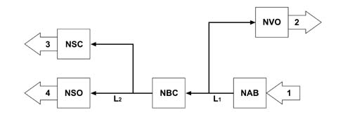
- 1 Passenger air bag inhibition on signal
- 2 Acoustic signal
- 3 Signal on NQS display
- 4 Passenger air bag disabled warning light on
- L1 - VAN CAR 1 network
- L2 - VAN Comfort
The information on the inhibition state of the passenger air bag is managed by the NAB, whilst the command to switch on the passenger air bag disabled warning light is produced by the NBC on the VAN Confort network (the NSO operates the passenger air bag disabled warning light on the basis of the command received).
The inhibition of the passenger air bag causes a message to be displayed on the screen and the steering column switch unit module produces an acoustic warning. The NBC manages the switching of the displays and sends a display command to the NSO.
the switch is not operated with the ignition key ON (e.g. using the second key). In this case, the electronic control unit saves an error, indicates it by turning on the air bag system fault warning light and deactivates the module.
Side impact satellite sensors
View of location of left sensor
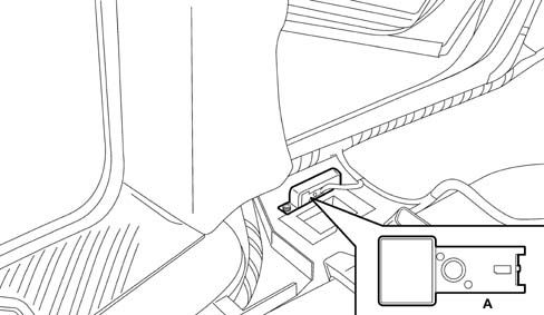
- A - Satellite side impact sensors
The side protection system consists of the airbags and also an electronic control circuit that ensures the system operates correctly. There are two satellite sensors (one on each side) containing an accelerometer, fastened to the underbody close to the front side pillar, which measure the acceleration resulting from a side impact.
A pin on the rear part of the sensor is used to position the sensor correctly in its seat. The case also contains a connection point for connectoin to the electrical system (green connector).
Operation
If the acceleration value measured by the sensor gives rise to a certain level being exceeded, the information is sent to the air bag system control node. If the values measured do not exceed a certain acceleration level, the NAB controls the activation of the side air bags (window bags and side bag) on the side affected by the impact.
SIDE BAG modules
The following figure shows an assembly view
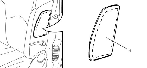
- 1 Side Bag housing cover
To ensure maximum front seat occupant safety in the case of side impact, side bag modules are installed on the seat backrests; they are fitted on the outside of the seat backrest, under the cover. This solution means that it is possible to always have the cushion in the optimum position for the occupant, whatever the seat adjustment.
This configuration is considered one of the most effective because it ensures the airbag is always in optimum position in relation to the occupant regardless of seat setting or occupant size.
The side bag is capable of mainly protecting the chest and abdomen, even if the seat occupant is not sitting properly because bag opening dynamics (11 litre volume) minimise the risk of body damage caused by impact with the airbag.
Operation
The module gas inflation generator is electrically activated by means of a signal from the NAB. Following this signal, a pyrotechnic activation is set off that causes the gas in the generator to expand and inflate the bag. The increase in bag volume breaks the plastic container in the set areas and causes the squab cover seams to yield along the preset sections to allow the bag to emerge correctly. The bag deflates immediately after being inflated by the gas thanks to the presence of s epcial opening.
It is not possible to carry out operations on seats fitted with air bags, apart from seat removal/refitting. It is strictly forbidden to dismantle seats fitted with air bags. This operation must be carried by trained, authorised technical personnel.
Do not cover the front seat squab with extra covers.
Do not wash the seat squab with water or steam under pressure.
WINDOW BAG module (side blind AIR BAG)
Assembly view
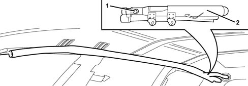
- 1 Connector
- 2 Gas generator
All versions of the car come with a system for protecting the head of front and rear side occupants in the first, second and third rows.
The head protection air bags (i.e. window bags) work in conjunction with the front air bags to offer front seat occupants the best possible protection in the case of impact. They also eliminate the risk of injury to arms and shoulders and protect the heads of rear side occupants.
Of all the different types of window bag, the drop-down type offers the best performance due to the extensive area covered and its ability to support itself even in the absence of a backing if the side windows break.
Composition
The window bag module consists of:
- a gas generator secured by mounts to the rear car pillar;
- a flexible pipe in permeable cloth secured by a band to the gas generator that diffuses the gas evenly over the entire length of the bag;
- a bag of about 48 litres in volume secured to the gas generator together with a flexible pipe. It is made out of nylon (PA 6.6) and folded inside a containment sleeve. When inflated, the bag is designed to ensure impact energy is correctly absorbed while maintaining the occupant´s head at an appropriate disatnce from the impact area. Once inflation is completed, gas is expelled immediately through the porous fabric.
- easy-opening plastic clips that secure the bag to the ceiling rail;
- a retaining belt that holds the bag in position once inflated;
- a connector for connection to the electrical system;
- a warning plate with instructions.
Operation
The module gas inflation generator is electrically activated by means of a signal from the NAB. Following this signal, a pyrotechnic activation is set off that causes the gas in the generator to expand. The expanding gas emerges through special openings and is distributed evenly along the length of the bag through the hose to make the bag inflate. the increase in bag volume causes the fastening container to break, the sleeve seams to yield and the trim to open. Everything is arranged so that the bag emerges correctly downward. The bag is made to inflate correctly by a retaining belt on the front end of the bag. When fully inflated, the bag is in an optimal position to protect the occupant. The bag deflates immediately after being inflated by the gas because the fabric is permeable.
Parts & tools for this job For 2002 Fiat Ulysse
- TOOLOBD2 scanner with SRSSearch: OBD2 scanner ABS SRS
- TOOLTrim removal tool kitSearch: trim removal tool kit
Links open Amazon search results in a new tab. As an Amazon Associate I earn from qualifying purchases.