
Ultrasound parking detection system
- Make
- Fiat
- Model
- Ulysse Factory Service Manual
- Year
- 2002–2010
- Section
- Instrument/gauge electrical circuits › Ultrasound parking detection system
ULTRASOUND PARKING DETECTION SYSTEM
INTRODUCTION
The parking assistance system provides the driver with distance information whilst reversing when they are approaching obstacles behind the vehicle; therefore the system helps when parking by identifying obstacles outside of the driver''s field of vision.
The information of the presence/distance of an obstacle is transmitted to the driver by means of acoustic warnings whose frequency depends on the distance of the obstacle.
The system is deactivated when the speed of the vehicle exceeds 30 km/h
Obstacle presence detection system display when reverse gear is engaged
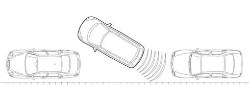
COMPOSITION
The parking assistance system fitted on the vehicle consists of an electronic control unit and 4 ultrasound sensors located on the rear bumper.
All the control unit input and output is protected against battery voltage and earth short circuits.
Parking Sensor Node (NSP)
The node is located on the right rear pillar near the speaker as illustrated below.
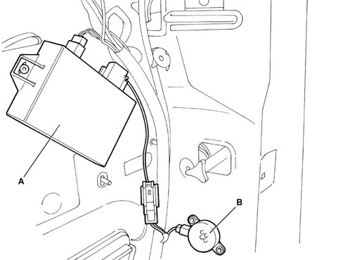
- A - Parking sensor node
- B - Acoustic indicator
The electronic node carries out the following functions:
- it receives the information that reverse gear has been engaged from the main electronic control unit
- it activates the sensors
- it processes the signals received by the sensors
- it controls the operation of the sensors
- it activates the speaker located in the right rear pillar
- it manages the fault diagnosis and test functions
Technical specifications
The main technical specifications of the electronic system are described below.
- Max absorption 100mA approx
- Weight 80g
- Stand-by absorption around 50 Ma
- Dimensions 24 X 65 X 85 mm
Discreet connections:
- Presence of trailer
- +12 V nominal supply (controlled by the ignition),
- Connections to rear sensors
NSP Pin Out
Black 18-way connector
| Pin | Function |
|---|---|
| 1 | + VAN |
| 2 | + (buzzer signal) |
| 3 | Not connected |
| 4 | Not connected |
| 5 | Date B |
| 6 | Not connected |
| 7 | Earth |
| 8 | Not connected |
| 9 | Not connected |
| 10 | - (buzzer signal) |
| 11 | Not connected |
| 12 | Not connected |
| 13 | Not connected |
| 14 | Date |
| 15 | Centre asx sensor signal |
| 16 | Centre adx sensor signal |
| 17 | Asx sensor signal |
| 18 | Adx sensor signal |
Black 6-way connector
| Pin | Function |
|---|---|
| 1 | Centre pdx sensor signal |
| 2 | Psx sensor signal |
| 3 | Pdx sensor signal |
| 4 | Rear sensor signal + |
| 5 | Centre pdx sensor signal |
| 6 | Rear sensor signal - |
ULTRASOUND SENSORS
The sensor is an ultrasound transducer which acts as an intelligent transmitter and receiver of ultrasound impulses; both the frequency and the voltage of the impulses are generated in the transducer.
The impulses produced are reflected by any obstacles; the transducer therefore receives an echo: the time measured between the emission and the echo alloes the distance of the obstacle to be defined.
The sensors all have the same electrical and mechanical properties; the maximum detection distance for each sensor can be adjusted using software according to the location of the actual sensor.
The arrangement of the parking sensors in the rear bumper is illustrated below.
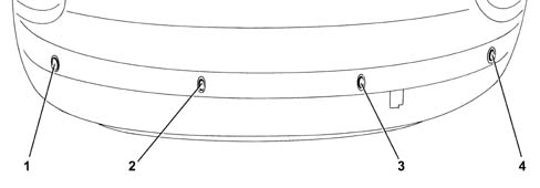
- 1,2,3,4 - Parking sensors
Main technical specifications
The main specifications of the obstacle sensors are:
- Maximum distance at the centre 1.5 m
- Maximum distance at the side 0.6 m
- Minimum / maximum distance 0.25 %divide; 1.5 m
- Max absorption 5 mA
- Weight 35 g
The power supply for the sensors is protected by an electronic fuse; the sensors are also fitted with hermetic connectors.
Input signals via VAN Confort network:
- Vehicle speed
- Reverse gear engaged
Output signals via VAN Confort network:
- horn via speaker (on right rear pillar)
OPERATION
The operating logic for the system in accordance with the multiplex network is illustrated below.
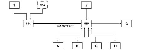
- 1 Reverse gear engagement signal
- 2 Trailer power supply signal
- 3 Buzzer
When the control unit is switched on (ignition ON) an autodiagnostic test and a test on all the peripheral functions are carried out. the system is ready to use in under 0.5 seconds.
When reverse gear is engaged, the sensors are activated and, if there is an obstacle, the buzzer produces a warning light whose frequency increases as the obstacle gets closer.
MEASURING DISTANCE OF OBSTACLES
The electronic control unit controls the sensors which convert the control unit electrical signals into ultrasound signals at a rhythm of 10 measuring processes per second.
The signal, reflected by any obstacles, is received by the sensor and the control unit compares the signal transmitted with the one rececived and, using suitable algorhythms, calculates the time elapsed between the issue of the signal and the reception of the echo (flight time). This information is translated into distance and communicated to the driver by means of sounds whose frequency is inversely proportional to the distance from the obstacle.
Each measuring cycle involves checking that the entire system is working properly.
OBSTACLE DISTANCE SIGNALS
The control unit processes the information supplied by the 4 rear sensors activating the vehicle''s audio speaker irrespective of whether this system is ON/OFF.
During the warning signals, the programme which may be in the process of being transmitted via the audio system is muted. The tone produced by the speakers advises the driver that the vehicle is getting close to an obstacle; the tone lasts for 75 ms, whilst the pause between the tones is directly proportional to the distance of the obstacle: impulses in rapid succession indicate that an obstacle is very close; a continuous tone indicates that the obstacle is less tthan 25 cm away. The acoustic signal stops immediately if the distance of the obstacle increases.
The table below indicates the minimum dimensions of an obstacle that can be detected by the sensors depending on the distance.
| Detection distance | 80 cm | 100 cm | 120 cm | 140 cm |
|---|---|---|---|---|
| Diameter of the obstacle that can be detected | 1 cm | 2 cm | 4 cm | 6 cm |
if a trailer is fitted, there is no signal; in effect, switching on the trailer electrical socket automatically excludes the operation of the sensors.
The operating area of the sensor is illustrated below
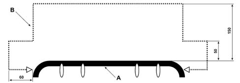
- A - Rear bumper
- B - Area (the measurements are in cm)
Parts & tools for this job For 2002 Fiat Ulysse
- TOOLDigital multimeterSearch: automotive digital multimeter
- PARTAssorted fuse kitSearch: car fuse assortment kit
- TOOLWire crimper and connector kitSearch: wire crimper connector kit
Links open Amazon search results in a new tab. As an Amazon Associate I earn from qualifying purchases.