
Tyre inflation pressure sensor
- Make
- Fiat
- Model
- Ulysse Factory Service Manual
- Year
- 2002–2010
- Section
- Instrument/gauge electrical circuits › Tyre inflation pressure sensor
TYRE INFLATION PRESSURE SENSOR
INTRODUCTION
A loss in tyre inflation pressure can result in serious problems:
- Burst tyre
- A considerable deterioration in the vehicle''s road holding and braking stability.
- Irregular, rapid wear of the tyres.
- Increased fuel consumption.
Currently there is no device that informs the driver of a fall in the tyre inflation pressure; the insufficient pressure warning system is designed to meet this need by constantly checking the four wheels. In particular, the device has the task of constantly monitoring the three pressure states (normal, deflated, punctured) and whether a wheel(s) is(are) missing.
The information is displayed both via the NSO (milomter warning lights node) by the STOP warning light coming on and via the NSC (multifunction screen node) in the form of a message in the display.
Composition
The system consists of:
- 4 pressure sensors inside the wheels transmitting at radiofrequency which allow a pressure, compensated for by the temperature of the wheels, to be measured (a variation in temperature of between -30°C and +70°C translates into a variation of 0.3 bar).
- 1 R.F. signals reception and management control unit located inside the steering column switch unit.
The reception control unit also analyzes the correct operation of each sensor following no response from the sensor (malfunction or batteries run down) or if new sensors are being programmed.
The sensors are designed to prevent possible false alarms caused by differences in pressure due to climatic and environmental conditions during the normal use of the vehicle.
the wheel control system does not check the spare wheel, does not deal with over inflation and does not allow which wheel(s) has(have) the problem to be precisely identified.
The product cannot be used in Japan, the USA, Israel, Australia and New Zealand and all countries which allow the use of RF devices with different frequency and emission ranges from Europe.
Operation
The structure of the system is illustrated below
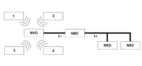
- 1,2,3,4 - Tyre pressure sensors
- L1 - VAN CAR 1 network
- L2 - Van Confort network
- NVO - Steering wheel node
- NBC - Body Computer Node
- NSO - Milometer Warning Lights Node
- NSC - Multifunction screen node
The sensor operating logic is mainly managed by the NBC which has the task of co-ordinating the various nodes and managing the associated functions.
The NVO acquires the pressure information required from the 4 sensors by means of reception control unit and sends the "rough" signal to the NBC.
The Body Computer Node processes the information from the NVO in detail using the following functions:
- it processes a possible puncture or insufficient inflation pressure,
- it determines the number of sensors missing
- it determines a rapid fall in pressure, a fairly rapid fall in pressure, a punctured wheel, a deflated wheel or incorrect pressure
- it memorizes wheel worn sender unit module battery" and "wheel sender unit module not read" faults.
Depending on the alarm in progress, the NBC activates the various warning lights in accordance with the diagram below.
Puncture alarm:
- The NBC detects a puncture alarm via the steering column switch unit module NVO
- The NSO (milometer warning lights node) lights up the STOP warning light when commanded by the NBC.
- The puncture alarm causes a message to be displayed on the screen and the steering column switch unit module produces an acoustic warning.
Insufficient inflation
- The NBC detects a puncture alarm via the steering column switch unit module NVO
- The insufficient inflation alarm causes a message to be displayed on the screen and the steering column switch unit module produces an acoustic warning.
Detection of tyre inflation pressure fault:
- The tyre inflation pressure alarm causes a message to be displayed on the screen and the steering column switch unit module produces an acoustic warning.
The fall in pressure compared with the recommended pressure of 3.5 bar (set in the factory), until the tyre is considered to be deflated, is 0.3 - 0.5 bar, beyond this value the wheel is considered to have a puncture.
Pressure sensor
The pressure sensor is illustrated in the diagram below
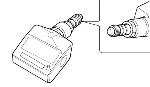
It is a device that monitors the pressure inside the tyre through a dedicated sensor which is linked to an electronic circuit for acquiring and processing the signals; it is has a section specially designed for transmitting radiofrequency signals at 433.92 MHz and a centrifugal switch for checking the rotation of the wheel.
The signals transmitted are then received by a reception control unit dedicated to transferring danger information. The sensor is supplied by a lithium battery that lasts 10 years in normal vehicle usage conditions. A system that checks the state of the battery guarantees that there is an alarm at least 3 months before it is completely run down.
Each sensor is also equipped with an identification code that is transmitted to the tyre pressure control unit which memorizes it.
technical data:
- Maximum pressure range measured between 0.25 and 3.5 bar with a
- Maximum pressure resolution 0.014 bar
- Frequency 433.92 MHz, 90 Kh
Operating procedure
The presence of a switch (incorporated in the sensor) that is sensitive to the centrifugal force exerted by the rotation of the wheel, makes it possible to determine whether the vehicle is moving or stationary.
This involves two data transmission and processing modes:
- vehicle moving mode;
- vehicle stationary mode.
Vehicle moving mode
The centrifual switch closes following the rotation of the wheel before a speed of 35 Km/h is reached or a maximum of 15 seconds after this level is passed. After it closes, the sensor measures the pressure and transmits the data immediately.
During this stage, the standard pressure monitoring takes place every 15 seconds and the information is systematically transmitted within 15 - 21 minutes as long as the pressure values remain within the normal range. When an excessive fall in pressure is detected, the transmission takes place every 5 seconds.
Vehicle stationary mode
The shift to this conformation takes place 30 seconds after the vehicle has stopped with the centrifugal switch open. The sensor systematically checks the pressure every 15 minutes and transmits the signal within 65 minutes. If pressure irregularities are detected, the transmission takes place in the same way as for the "vehicle moving mode" and the first time the ignition is turned ON the customer is advised of the problem through the NSO and the multifunction screen.
there is an opening in the sensor to allow the pressure to be measured and it should not be obstructed (avoid using spray canisters for inflation and fast repairs to the rubber)
Fitting the sensor
The tyre pressure sensor is fitted at the rear of the tyre inflation pressure valve. Fitting and dismantling should be carried out by specialized personnel using the correct equipment so that the sensor is not permanently damaged.
Receiver control unit
This control unit is incorporated in the NVO with a 433.92 MHz radiofrequency receiver with the identification codes for the 4 sensors memorized so that it is capable of carrying out each pressure check for each individual tyre. It is a specific module for the insufficient inflation function and the aerial is incorporated in the steering column switch unit module.
Diagnostic function
It is possible through the fault diagnosis to know the number of wheels that have a problem but not their precise location on the vehicle. A pressure of 2.31 bar is programmed in the NBC as the standard value but it can be reprogrammed and a different value set using the Examiner.
Parts & tools for this job For 2002 Fiat Ulysse
- TOOLOBD2 scannerSearch: OBD2 scanner
- TOOLDigital multimeterSearch: automotive digital multimeter
- TOOLBack-probe test leadsSearch: back probe test leads
Links open Amazon search results in a new tab. As an Amazon Associate I earn from qualifying purchases.