
Steering wheel node (nvo)
- Make
- Fiat
- Model
- Ulysse Factory Service Manual
- Year
- 2002–2010
- Section
- Instrument/gauge electrical circuits › Steering wheel node (nvo)
STEERING WHEEL NODE (NVO)
INTRODUCTION
The NVO module is an interface that retransmits the actions carried out by the user by means of the steering column switch unit controls. The NVO communicates with the NBC via the VAN CAR 1, but the processing remains the responsibility of the NBC which is the true heart of the system.
The steering column switch unit module, in the main, manages the function of collecting the RF messages for the remote controls and sender units for the insufficient tyre inflation pressure, transmits information concerning the steering wheel angle and operates the transponder aerial.
The NVO guarantees the connection with the NBC for the following functions:
- management of the switches (lighting, direction indicators, windscreen wipers, horn, radio controls, speed regulator).
- emission of warning signals (buzzer built into the steering column switch unit module).
- dialogue with the transponder coil (aerial).
- acquisition of remote control RF signal.
- acquisition of insufficient inflation pressure function RF signal.
- Air Bag connection.
- steering wheel angle sensor information.
- VAN interface.
- system diagnosis.
The steering column switch unit is supplied by the + VAN and the RF receiver function receives a permanent + 12V supply.
The system activates the NBC each time the following actions take place at the steering column switch unit:
- activation of the horn
- headlamp switching on and flashing
- receipt of a message from the remote control concerning the opening of the doors.
The steering column switch unit module moves to stand-by when there is an interruption in the +VAN.
PIN OUT
The NVO Pin Out is illustrated in the table below
NVO: VAN function 6-way grey connector
| Pin | Function |
|---|---|
| 1 | Data b |
| 2 | not connected |
| 3 | Date |
| 4 | earth |
| 5 | + permanent |
| 6 | + VAN |
Transponder function 6-way brown connector
| Pin | Function |
|---|---|
| 1 | not connected |
| 2 | not connected |
| 3 | not connected |
| 4 | Aerial |
| 5 | not connected |
| 6 | Aerial |
Steering angle sensor function 6-way black connector
| Pin | Function |
|---|---|
| 1 | S 3 |
| 2 | not connected |
| 3 | Earth |
| 4 | VCC |
| 5 | S 2 |
| 6 | S 1 |
ESP sensor function 6-way blue connector
| Pin | Function |
|---|---|
| 1 | CAN L |
| 2 | Earth |
| 3 | CAN H |
| 4 | VCC |
| 5 | S 2 |
| 6 | S 1 |
Air Bag chamber function 2-way brown connector
| Pin | Function |
|---|---|
| 1 | Not indicated |
| 2 | Not indicated |
Air Bag chamber function 2-way blue connector
| Pin | Function |
|---|---|
| 1 | Not indicated |
| 2 | Not indicated |
Horn function 5-way elbow connector
| Pin | Function |
|---|---|
| 1 | not connected |
| 2 | not connected |
| 3 | not connected |
| 4 | Horn |
| 5 | Earth |
Air Bag igniter function 2-way blue connector B
| Pin | Function |
|---|---|
| 1 | Not indicated |
| 2 | Not indicated |
Air Bag igniter function 2-way blue connector C
| Pin | Function |
|---|---|
| 1 | Not indicated |
| 2 | Not indicated |
Diagnostic function:
- RF receiver fault
- Transponder fault
- Lights operation fault
- Windscreen wiper operation fault
COMPOSITION
The steering column switch unit module is illustrated in the diagram
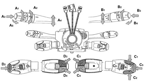
The system groups together the following MAIN CONTROLS.
Lighting/signalling controls:
- A1 lighting: 0, side lights, dipped headlamps (rotary ring nut)
- A2 Front and rear fog lights (rotary ring nut)
- A3 Automatic activation/deactivation of side lights and dipped headlamps (button)
- A4 Direction indicator
- A5 Main beam headlamps
Rain sensor windscreen wiper controls
- B1 Front windscreen wipers
- B2 Rearscreen wipers
- B3 On-board computer
- B4 Automatic windscreen wiper activation
SECONDARY CONTROLS
Cruise Control system controls:
- D1 Drive / stop
- D2 Deactivation / reactivation
- D3 Speed +
- D4 Speed -
Radio controls
- C1 Increasing station search mode
- C2 Decreasing station search mode
- C3 Volume +
- C4 Volume
- C3+C4 No volume
- C5 Control button: Mode/Telephone
- C6 Programmed stations search ring nut
Transponder and key presence function
the steering column switch unit module manages the dialogue between the key-remote control and the built in receiver. The NBC carries out the recognition and learning of the electronic key.
Cruise Control lever Pin Out
The position of the cruise control lever connector is illustrated in the diagram below.
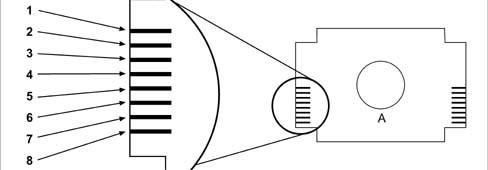
Cruise Control Pin Out Table
| Pin | Function |
|---|---|
| 1 | not connected |
| 2 | not connected |
| 3 | Driving / Stop |
| 4 | Joint |
| 5 | Speed |
| 6 | Deactivation / Resumption |
| 7 | Speed +/ Set |
| 8 | Not assigned (but connected) |
Radio lever pin out
The position of the radio lever is illustrated in the diagram below
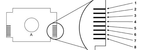
Cruise Control Pin Out Table
| Pin | Function |
|---|---|
| 1 | Forward search |
| 2 | Volume + |
| 3 | Mode / Tel |
| 4 | Volume - |
| 5 | Backwards search |
| 6 | Joint |
| 7 | Ring nut signal S1 |
| 8 | Ring nut signal S1 |
Parts & tools for this job For 2002 Fiat Ulysse
- TOOLTie rod end toolSearch: tie rod end puller
- TOOLBall joint separatorSearch: ball joint separator
- FLUIDPower steering fluidSearch: Fiat power steering fluid
Links open Amazon search results in a new tab. As an Amazon Associate I earn from qualifying purchases.