
Exterior and interior lighting
- Make
- Fiat
- Model
- Ulysse Factory Service Manual
- Year
- 2002–2010
- Section
- Instrument/gauge electrical circuits › Exterior and interior lighting
EXTERIOR AND INTERIOR LIGHTING
COMPONENTS
The vehicle is equipped with:
- a function that automatically switches on the dipped headlamps when light conditions are poor.
- the function known as Parking (follow me home) keeps the exterior lights on for a timed period after the ignition key has been removed. If the light is below 850 LUX, the dipped headlamps remain on for 45 seconds.
- after having turned the ignition OFF, a flash switches on the dipped headlamps for 1 minute. It is possible to interrupt this by operating the headlamp flasher switch again (this function does not control the buzzer for lights remaining on when the doors are opened).
- A funciton for automatically switching on the direction indicators in the case of strong deceleration or an impact with the activation of a two tone horn.
The direction indicators are located:
- in the door mirrors,
- in the front and rear light clusters.
The rear light clusters include:
- the direction indicators,
- the brake lights, the 3rd brake light is located at the top of the tailgate,
- the reversing lights,
- the rear fog lamps.
INTERIOR LIGHTING
The table below contains the specifications of the bulbs used for the interior lighting.
| Function | Power | Type |
|---|---|---|
| Passenger compartment ceiling lights | 5W | W5W |
| Luggage compartment courtesy lights | 5W | W5W |
| Glove compartment courtesy light | 5W | W5W |
| Vanity mirror courtesy lights | 5W | W5W |
| Puddle lights | 5W | W5W |
The interior lighting is ensured by the management of the following equipment:
- one courtesy light in the 1st row,
- one courtesy light in the 2nd row,
- one courtesy light in the 3rd row,
- one light in the driver and passenger sun visor,
- one light in the glove compartment,
- one light in the driver''s front door,
- one light in the passenger front door,
- two lights in the luggage compartment.
The switching on and off of the courtesy lights takes place gradually (variation in the voltage at the bulb terminals), unless they are switched on manually. The map reading lights in the front courtesy light, the lights in the luggage compartment, glove compartment, vanity mirrors and front doors do not switch on and off gradually.
The switching on of the interior lighting is activated by:
- pressing the centrally operated switch (front courtesy light console),
- opening one of the four doors or the boot,
- extracting the ignition key within a minute of a break in the +ACC,
- unlocking the doors (if the key is not in the anti-theft function position and is in position +ACC),
- vehicle location function.
The switching off of the interior lighting is activated by:
- moving the central control switch to the "forced switching off" position
- closing the door
- locking/superlocking the vehicle
- inserting the key for starting the engine (moving from +ACC to +APC).
The courtesy light function is divided into three states:
- Rest state: courtesy light function off.
- Brief lighting: lighting timed for a period of 30 seconds.
- Long lighting: lighting timed for a period of 10 minutes.
The courtesy light switches on gradually over a period of 1 second.
It switches off gradually in 4 seconds.
All the lights operate with a delay timer to prevent the battery being run down.
Courtesy light lighting when the key is extracted from the ignition:
The detection of the presence of the key is activated for 1 minute after the +ACC interruption.
When this timed period has elapsed, the lighting function when the key is extracted is no longer activated.
The boot lighting function: is guaranteed by two 5W bulbs, controlled by the NBC depending on the position of the three position switch and the status of the doors.
The vanity mirror lighting function: is guaranteed by 1 component fitted with 2 x 2W bulbs, the bulbs light up when the sun visors containing the vanity mirrors are opened and the ignition is in the "ACC" or "MAR" position.
The glove compartment lighting function: is guaranteed by a 5W bulb with the ignition in the "ACC" or "MAR" position.
The front door lighting function: is guaranteed by two 5W bulbs.
The vehicle is fitted with a ceiling courtesy light comprising two built in map reading lights.
The spot lights operate from the +ACC
The diagram below illustrates the top of the range ceiling courtesy light
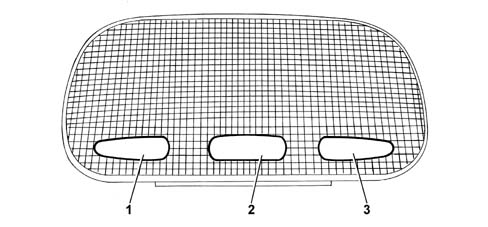
- 1 Map reading light on switch
- 2 Courtesy light on switch
- 3 Map reading light on switch
The diagram below illustrates the bottom of the range ceiling courtesy light
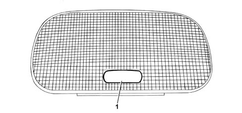
- 1 Courtesy light on switch
Operation
The courtesy lights are controlled by a three position switch:
- automatic switching on,
- constantly on,
- permanently off.
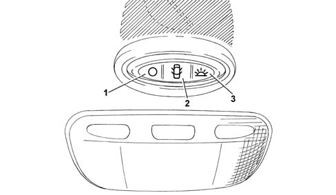
- 1 courtesy light switching off
- 2 courtesy light switching on with doors open
- 3 courtesy light switching on +ACC
Front and rear courtesy lights function
The NBC acquires the command for the button and manages the operation of the courtesy light.
For the management of the automatic switching on of the courtesy light, the NBC uses information relating to the status of the doors (produced by the door nodes), the request for locking/unlocking and the presence of the key.
Map reading lights function
Power supply is possible with the key in the +ACC position and the bulb is controlled directly by the button.
Interior equipment brightness adjustment
The NQS acquires information from the light dimmer, determines the lighting level required and then transfers the information to the NBC.
The NBC knows the status of the lights (day/night).
The NBC controls the switching on of the lights indicating the position of the following (with no dimmer function):
- ashtray,
- door switches,
- seat switches,
- various buttons.
The NBC transmits information concerning the lighting level to the NQS, to the radio and to the NIT, to the NCL (Climate Control Node) and to the NSC (Multifunction Screen Node) by means of the VAN confort network for the lighting or lighting adjustment.
EXTERIOR LIGHTING
The vehicle is equipped with the following range of lamps:
- front side lights and rear number plate light,
- front and are direction indicators and side repeaters (located at the bottom of the door mirrors),
- dipped headlamps,
- main beam headlamps,
- fog lights and rear fog lamps.
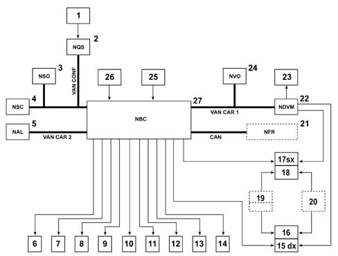
- 1 Hazard warning lights switch
- 2 Instrument Panel Node (NQS) (controls the operation of the warning lights)
- 3 Milometer Warning Lights Node (NSO) (switches the warning lights on/off)
- 4 Multifunction Screen Node (NSC) (Displays messages)
- 5 Alarm node (NAL) (manages the alarm function)
- 6 3rd brake light
- 7 Right front side light
- 8 Left front side light
- 9 Right rear light
- 10 Left rear light
- 11 Right door courtesy light
- 12 Left door courtesy light
- 13 Right side direction indicator
- 14 Left side direction indicator
- 15 Right front light cluster
- 16 Right headlamp alignment correction motor
- 17 Left front light cluster
- 18 Left headlamp alignment correction motor
- 19 Headlamp alignment correction sensors (for xenon lamps)
- 20 Manual headlamp alignment corrector (for halogen lamps)
- 21 Brake Node (NFR) (calculates the speed of the vehicle)
- 22 Engine Compartment Junction Unit Node (NDVM) (controls the main beam headlamps, dipped headlamps and fog lights)
- 23 Buzzer
- 24 Steering Wheel Node (NVO) (acquires commands for the steering column switch unit and transmits them to the NBC)
- 25 Rain sensor
- 26 Solar rays sensor
- 27 Body Computer Node (NBC)
The table below contains the specifications of the bulbs used for the exterior lighting.
| Function | Power | Type | |
|---|---|---|---|
| Front side lights | 5W | W5W | |
| Dipped headlamps | halogen bulbs | 55W | H7 |
| Dipped headlamps | xenon gas discharge bulbs | 35W | D15 |
| Main beam headlamps | 55W | H7 | |
| Front fog lights | 55W | H3 | |
| Direction indicators | front | 21W | PY21W |
| Direction indicators | side | 5W | WY5W |
| Direction indicators | rear | 21W | PY21W |
| Brake lights and rear side lights | 21W/5W | P21/5W | |
| 3rd brake light | 5W | W5WF14 | |
| Reverse gear | 21W | P21W | |
| Rear fog lamps | 21W | P21W | |
| Number plate light | 5W | W5W | |
Components
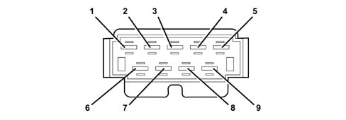
Front light clusters: equipped with a black 9-way connector.
| Pin | Function |
|---|---|
| 1 | DIPPED HEADLAMPS power supply: (L/R) |
| 2 | MAIN BEAM HEADLAMPS (L/R) power supply |
| 3 | Side lights power supply: (L/R) |
| 4 | Joint EARTH |
| 5 | DIAGNOSTIC socket LINE |
| 6 | FOG LIGHTS control, +APC NBC |
| 7 | Headlamp alignment correction control (for xenon lamps) |
| 8 | DIRECTION INDICATORS control: (L/R) |
| 9 | ALIGNMENT CORRECTOR control earth (for xenon lamps) |
Ignition switch: incorporated in the steering column switch unit module.
Headlamp alignment correction motor: incorporated in the lamp.
Headlamp alignment manual correction: makes it possible to adjust the four lighting positions manually: 0, 1, 2 and 3.
The switch is located to the left of the steering wheel, at the bottom of the dashboard.
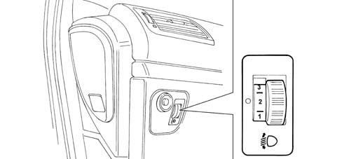
Headlamp alignment automatic correction (for xenon lamps): on vehicles fitted with xenon lamps, the automatic correction of the headlamp alignment is managed by the headlamp control units based on the signals produced by the two sensors which measure the angle of the bodyshell.
The NBC: manages the direct operation of the bulbs and the NDVM control for the power supply for the dipped headlamps, main beam headlamps and fog lights.
The solar ray sensor: is fastened to the dashborad and transmits the information detected directly to the NBC for the management of the function that automatically switches on the lights and the climate control system.
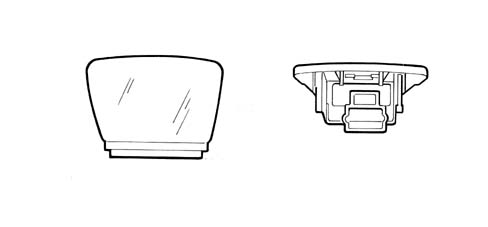
It manages the lighting and the switching off of:
- the front and rear side lights (and the number plate light).
- the dipped headlamps.
When the automatic switching on function is activated, the system manages the switching on and off of the lights according to:
- the exterior light conditions (day/night)
- the presence of a tunnel or poorly lit car park
- area in prolonged shade (e.g. woodland)
- the automatic windscreen wiping system.
The system does not ask for the lights to be switched on whilst driving under a bridge or in a partly shaded area.
The moment the vehicle stops, if the light conditions are very poor, the system keeps the lights on for long enough to allow the user to get out of the vehicle and do anything they may need to do.
manual controls for switching the lights on always take precendence.
Operation in fault conditions.
If there is a fault in the system, this does not cause the lights to go out inappropriately.
If the fault is detected when starting up, the function for automatically switching the lights on is immediately inhibited and the driver is advised of this.
No type of fault in the automatic light management system has any effect on the manual operation.
The system does not take into account the colour of the windscreen.
Supply circuit: The sensor receives a +5V power supply and the system does not have a fuse.
The solar ray sensor contains the following sensors:
- Twilight sensor - a sensor that sends information concerning the outside light conditions
- Tunner sensor - a sensor that sends information concerning the light level in front of the vehicle.
Electrical output signals:
- Twighlight (used for the automatic function for switching on the lights)
- Tunnel (used for the automatic function for switching on the lights)
- Solar (used for the climate control system)
Black 6-way connector pin out.
| Pin | Function |
|---|---|
| 1 | Tunnel signal |
| 2 | Twilight signal |
| 3 | Solar signal |
| 4 | Not used |
| 5 | Not used |
| 6 | Earth |
Diode polarization principle:
Diodes supply a current proportional to the lighting. The signal measured by the NBC is a voltage proportional to the current (and consequently the brightness detected by the photodiode).
Functional distribution and wiring diagrams
Switching on of side lights and no. plate lights
The command is acquired by the NBC via the steering column switch unit module.
The NBC controls the following directly:
- the front side lights,
- the rear side lights,
- the number plate light.
It sends the lights on/off status to the network and controls the warning light LEDs.
The connections at the NBC for the management of the side lights and the number plate light are illustrated in the table below.
| Function | Pin | Connector |
|---|---|---|
| Brightness sensor | 6 | 40-way white |
| Brightness sensor | 8 | 40-way white |
| Left front light | 13 | 16-way green |
| Right front light | 15 | 16-way green |
| Left rear light | 15 | 16-way grey |
| Right rear light | 11 | 16-way grey |
Lights left on buzzer
Starting with the information on the state of the driver''s door node, key position, lighting state, manual or automatic lighting control status, the NBC determines whether it is necessary to send a command to the buzzer via the steering column switch unit module.
The VAN CAR1 network remains activated as long as the lights are on.
Dipped/main beam headlamp switching on
The acquisition of the driver''s command remains identical to that for the side lights.
The NBC sends the command to:
- switch on the dipped or main beam headlamps to the NDVM via the network; the NDVM activates the relay involved,
- switch on the dipped or main beam headlamps warning light in the instrument panel via the VAN CONFORT network.
The headlamps activated command signal, if necessary, via the VAN CAR1 network.
If there is a communication problem between the NVO and the NBC the following is allowed:
- a shift to auto mode, if the vehicle is equipped with that function,
- on a vehicle not fitted with the auto function, the side lights are switched on during starting or the dipped headlamps with the engine running.
If the NDVM is faulty, the dipped headlamps can be switched on or kept on with the engine running.
The connections at the NDVM for the management of the main beam and dipped headlamps are illustrated in the table below.
| Function | Pin | Connector |
|---|---|---|
| Left dipped headlamp | 15 | 16-way grey |
| Right dipped headlamp | 8 | 16-way grey |
| Left main beam headlamp | 7 | 16-way grey |
| Right main beam headlamp | 6 | 16-way grey |
Switching on of fog lights
The switching on of the fog lights is controlled by a relay operated by the NDVM. The logic for acquiring the command and the switching on of the warning light in the instrument panel are identical to the one used for the dipped headlamps or the main beam headlamps.
The control for switching on the rear fog lamps is carried out directly by the NBC after the acquisition of the command carried out via the NVO.
To switch the fog lights on: turn the ring nut on the left steering column switch unit upwards.
The first impulse, unstable position, controls the switching on of the front fog lights; the warning light in the instrument panel should come on.
The second impulse, unstable position, controls the switching on of the rear fog lamps; the warning light in the instrument panel should come on.
To switch off, turn the ring nut downwards, unstable position.
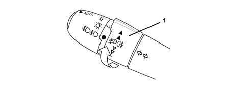
The connections at the NDVM for the management of the rear fog lamps are illustrated in the table below.
| Function | Pin | Connector |
|---|---|---|
| Rear fog lamp | 4 | 16-way black |
Headlamp manual alignment function
Depending on the action taken by the driver on the ring nut, the corrector will correct the angle of the headlamp, as necessary.
The connections at the manual headlamp alignment corrector are illustrated in the table below.
| Function | Pin | Connector |
|---|---|---|
| Alignment corrector position control | 2 | 3-way black |
Automatic switching on of lights
The aim of this function is to automatically control the switching on and off of the lighting system depending on the outside light conditions or the operation of the windscreen wiper system.
The level for switching on the lights corresponds to the moment when 30% of drivers would have activated the control on a vehicle not equipped with this automatic function.
The level for switching off the lights corresponds to the moment when 70% of drivers would have switched the lights off.
After switching off the engine, the lights remain on if the exterior light conditions dictate.
The detection parameters make it possible to distinguish between day and night, driving under a bridge, in a tunnel or in a poorly lit car park.
The system comprises the following components:
- a brightness sensor fitted on the dashboard.
- the NBC.
OPERATING PRINCIPLES
The automatic switching on function is only activated or deactivated with the key in the +ACC position by pressing the button at the end of the left steering column switch unit lever for at least 2 seconds.
An auditory warning produced by the NVO plus a message on the multifuction screen accompany the activation and deactivation of the automatic lighting function.
The manual control for switching on the side lights is only signalled by a pictogram.
The brightness information produced by the solar ray sensor is received directly by the NBC.
The intermittent, low speed, high speed and AUTO screen washing functions are activated after an automatic timed switching on.
The timed period is:
- 40 seconds for intermittent operation
- 10 seconds for the low speed
- 2 seconds for the high speed
The automatic interruption of the lighting is controlled 15 seconds after the screen washing function has stopped.
Switching on of reversing light
The switch is supplied with the key in the ON position; the NBC acquires control information and supplies the bulbs directly. This information is also sent via the VAN CONFORT network.
Switching on of brake lights
The rear lights are supplied directly by the NBC starting with the control information with the ignition ON.
The connections at the NBC for the management of the brake lights are illustrated in the table below.
| Function | Pin | Connector |
|---|---|---|
| Brake lights control | 1 | 16-way green |
| Left rear brake light | 10 | 16-way black |
| Right rear third brake light | 1 | 16-way black |
Automatic switching on of hazard warning lights
INTRODUCTION
The aim of this function is to improve safety whilst driving in traffic, automatically signalling sudden deceleration by switching the hazard warning lights on.
The lights can also be switched off automatically, depending on the vehicle parameters.
Automatic operation takes precedence over manual controls.
OPERATING PRINCIPLE
The system continuously measures vehicle acceleration when the engine is running. If this is below - 7m/s2 and the speed is above 40 km/h, the hazard warning lights are switched on automatically.
The lights are switched off automatically:
- automatically when the vehicle acceleration becomes decidedly positive,
- manually by pressing the hazard warning lights on/off button located at the bottom of the dashboard to the left of the steering wheel.
the automatic switching off mode is only possible if the switching on was in the automatic mode.
Switching the engine off does not have any effect on the switching off of the lights.
Switching on of danger signal
The NQS acquires the control for the hazard warning lights button and transmits it to the NBC via the VAN CONFORT network.
The NBC operates all the direction indicators directly, transmits the command to switch the direction indicator warning lights and the LED in the button on to the NQS and the command to operate the auditory warning (buzzer) to the NVO.
The operation of the button LED circuit is PWM to allow it to be lit up at night or to signal its activation.
In the case of an impact or for the management of the automatic switching on mode, the NBC uses the vehicle speed and longitudinal acceleration information via the CAN and the Air Bag Node information via the VAN CAR1 network.
Switching on of direction indicators
The NVO acquires the request to switch on the left or right direction indicator and transmits it to the NBC.
The management of the lights and the warning lights by the NBC is identical to the description for the danger signal.
The presence of a burnt out bulb produces a doubling of the frequency for switching on the lights for the direction indicator function only (2.5 Hertz instead of 1.25).
The fault diagnosis is carried out by the NBC by comparing the value of the current effectively absorbed compared with the rated value (47 W). There is no fault diagnosis for the side repeaters (5 W).
The fault diagnosis makes it possible to identify the side of the vehicle where the bulb has blown.
The connections at the NBC for the management of the direction indicators are illustrated in the table below.
| Function | Pin | Connector |
|---|---|---|
| Left front direction indicator | 9 | 40-way black |
| Right front direction indicator | 19 | 40-way black |
| Left rear direction indicator and left side repeater | 14 | 40-way black |
| Right rear direction indicator and right side repeater | 13 | 40-way black |
Vehicle exterior signal / Horn
The NVO acquires the request to activate the horn, if necessary, activating the VAN CAR1, and transmits the request to the NBC which controls a relay built into the NDVM via the network.
The NDVM operates via a wire.
The connections at the NDVM for the management of the horn are illustrated in the table below.
| Function | Pin | Connector |
|---|---|---|
| Horn | 15 | 16-way green |
| Horn | 7 | 16-way green |
DISCHARGE BULB
General remarks
This system provides the customer with:
- improved safety and minimal visual fatigue on account of it emission spectrum being close to daylight,
- improved driving comfort thanks to an increase in the lighting range; visibility is up to 120 metres with the dipped headlamps,
- greater reliability in terms of the life of the bubs thanks to the fact that there is no filament; these bulbs last four times as long as halogen bulbs,
- energy consumption reduced by 40%.
The table below contains comparative data for halogen bulbs and gas discharge bulbs.
| HALOGEN BULB | DISCHARGE BULB | |
|---|---|---|
| Flow (in lumen) | 1500 | 3200 |
| Life | 300 - 500 hours | 5000 hours approx |
| Power | 65 Watt | 35 Watt |
| Colour temperature (in degrees Kelvin) | 3200 dominant yellow | 4200 dominant blue |
| Voltage (stabilized) | 13.5 Volt | 85 Volt |
| Switching on time | 0.2 seconds | 0.5 secs if switching on straight from cold to hot |
The lighting system with gas discharge bulbs includes the automatic correction of the angle of the light beam in accordance with European legislation. The objective is based on keeping the light beam low irrespective of the vehicle load conditions to prevent dazzling the drivers of oncoming vehicles.
The headlamp washer function is always fitted on vehicles equipped with gas discharge headlamps.
Composition
The optical component consists of:
- 1 Electronic module,
- 1 5G type ignition module (built into the electronic module).
- 1 D1 type bulb
- 1 dual function dipped/main beam headlamps elliptical reflector
- 2 position sensors.
- 1 stepping motor
- 1 medium voltage (1 Kv approx) shielded beam (LAD).
- 1 low voltage internal beam.
D1 bulb: this comprises 2 electrodes, salt and high pressure gas: xenon.
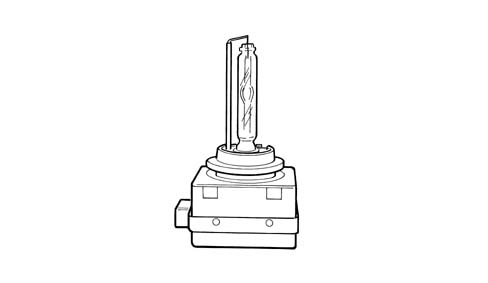
The main bulb components are illustrated in the diagram below.
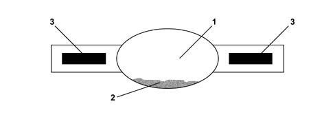
- 1 Xenon
- 2 Salts
- 3 Electrodes
The switching on stages for a xenon bulb are illustrated in the diagram below.
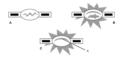
- A - Switching on stage
- B - Heating stage Evaporation of salts Max. intensity = 2.6 ampères
- C - Stabilized operation Duration of stabilization: 2 secs. Diffused power = 35 Watts + Bulb heating time: 30 to 40 seconds
- 1 Arc
Ignition module and electronic module
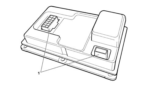
- 1 Connector
The ignition module forms part of the control unit and is fastened to the bottom of the lamp; it consists of a casing and an independently shielded beam fitted with specific connections on the bulb side and a computer that cannot be repaired.
The ignition module releases a voltage of 1Kv at the bulb D1 terminals during the switching on stage and then it supplies an alternating voltage at 250 Hz.
The transformation of 1Kv %rarr; 25 Kv is carried out inside the bulb D1 to ensure the production of the electric arc.
Its specifications are:
- power output: 35 watt,
- Operating voltage: 8.5 volt - 18 volt,
- Life: 3000 hours - 5000 hours.
Tilt sensors: these are fastened to one of the bodywork components and are connected to the front and rear suspension arms at the anti-roll bar by means of a system of connecting rods. They are designed to measure the position of the vehicle and their travel is ± 45 degrees.
The sensors provide a PWM (Pulse Width Modulation) type output voltage, i.e. a square wave signal with a frequency of 200Hz with a variable cyclical ratio. The cyclical ratio is proportional to the angle of the lever.
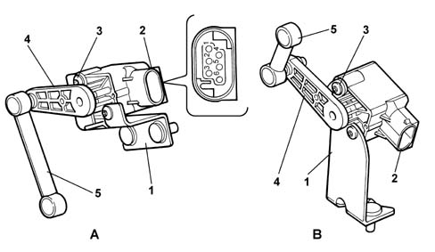
- A - Rear sensor
- B - Front sensor
- 1 Mounting bracket
- 2 Connector
- 3 Bracket sensor fastening
- 4 Lever
- 5 Connecting rod
| Pin | Function |
|---|---|
| 1 | Earth |
| 2 | Sensor selection |
| 3 | Not connected |
| 4 | PWM signal output |
| 5 | battery + |
| 6 | Not connected |
Headlamp alignment correctors; these consist of stepping motors fitted in the front headlamps. Each corrector is controlled by its own control unit.
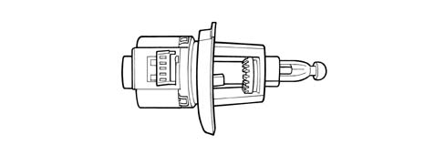
Operating principle
Starting with the information supplied by the sensors, the control unit determines the angular position of the vehicle Corrections to the angle of the light beam are made continuously when the headlamps are supplied.
Special precautions
Do not disconnect the bulb or ignition unit when voltage is present.
Never handle any components whatsoever when voltage is present.
Never handle a hot bulb (RISK OF GAS LEAKS).
If a component is defective, replace the OPTICAL UNIT.
The headlamps with gas discharge bulbs have a "WARNING, DANGER" label because handling these bulbs can be dangerous.
Connections
The pin out for the light cluster connector is illustrated in the table below.
| Pin | Function |
|---|---|
| 1 | Dipped headlamps power supply |
| 2 | Main beam headlamps power supply |
| 3 | Side lights power supply |
| 4 | Joint earth |
| 5 | K DIAG LINE (xenon) /Halogen corrector EARTH |
| 6 | Fog lights power supply, +15 NBC |
| 7 | Angle sensor information (xenon)/Halogen corrector control |
| 8 | Direction indicators power supply |
| 9 | + 15 (xenon) / +12 VOLT Halogen |
Parts & tools for this job For 2002 Fiat Ulysse
- PARTReplacement bulbsSearch: Fiat Ulysse 2002 bulbs
- TOOLDigital multimeterSearch: automotive digital multimeter
Links open Amazon search results in a new tab. As an Amazon Associate I earn from qualifying purchases.