
Anti-lock brake system – circuit diagram
- Make
- Land Rover
- Model
- Range Rover Classic Electrical Troubleshooting Manual
- Year
- 1995
- Section
- Circuit diagram › Anti-lock brake system – circuit diagram
‹ Prev Ignition and shift interlock – fault diagnosisNext › Anti-lock brake system – circuit diagram
Anti-lock brake systemAnti-lock brake system – circuit diagram
ANTI-LOCK BRAKE SYSTEM – CIRCUIT DIAGRAM
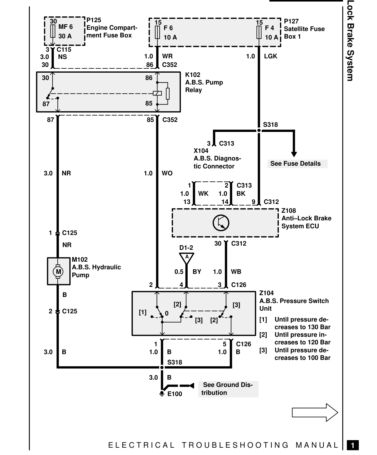
P125 30 15 MF 6 Engine Compart- F 6 ment Fuse Box 30 A 10 A 3 C115 1.0 WR 3.0 NS 30 86 C352
30 86
85 87
87 85 C352
1.0 WO 3.0 NR
1 C125 NR
M102 A.B.S. Hydraulic 0.5 M Pump 2 B [2] 2 C125 [1] 0
1 3.0 B 1.0 B S318
3.0 B
E100
E L E C T R I C A L
Anti-Lock Brake System P127 15 F 4 Satellite Fuse Box 1 10 A
1.0 LGK
K102 A.B.S. Pump Relay
S318
3 C313 X104 A.B.S. Diagnos- See Fuse Details tic Connector
1 2 C313 1.0 WK 1.0 BK 9 C312 13 14 Z108 Anti-Lock Brake System ECU
30 C312 D1-2 A
BY 1.0 WB
4 3 C126 Z104 A.B.S. Pressure Switch [3] Unit [1] Until pressure de- [3] [2] creases to 130 Bar [2] Until pressure in- creases to 120 Bar 5 C126 [3] Until pressure de- 1.0 B creases to 100 Bar
See Ground Dis- tribution
T R O U B L E S H O O T I N G M A N U A L
1
‹ Prev Ignition and shift interlock – fault diagnosisNext › Anti-lock brake system – circuit diagram
Parts & tools for this job For 1995 Land Rover Range Rover
- TOOLDigital multimeterSearch: automotive digital multimeter
- PARTAssorted fuse kitSearch: car fuse assortment kit
- TOOLWire crimper and connector kitSearch: wire crimper connector kit
Links open Amazon search results in a new tab. As an Amazon Associate I earn from qualifying purchases.