
Key information – circuit diagram
- Make
- Land Rover
- Model
- Range Rover Classic Electrical Troubleshooting Manual
- Year
- 1995
- Section
- Circuit diagram › Key information – circuit diagram
KEY INFORMATION – CIRCUIT DIAGRAM
KEY INFORMATION
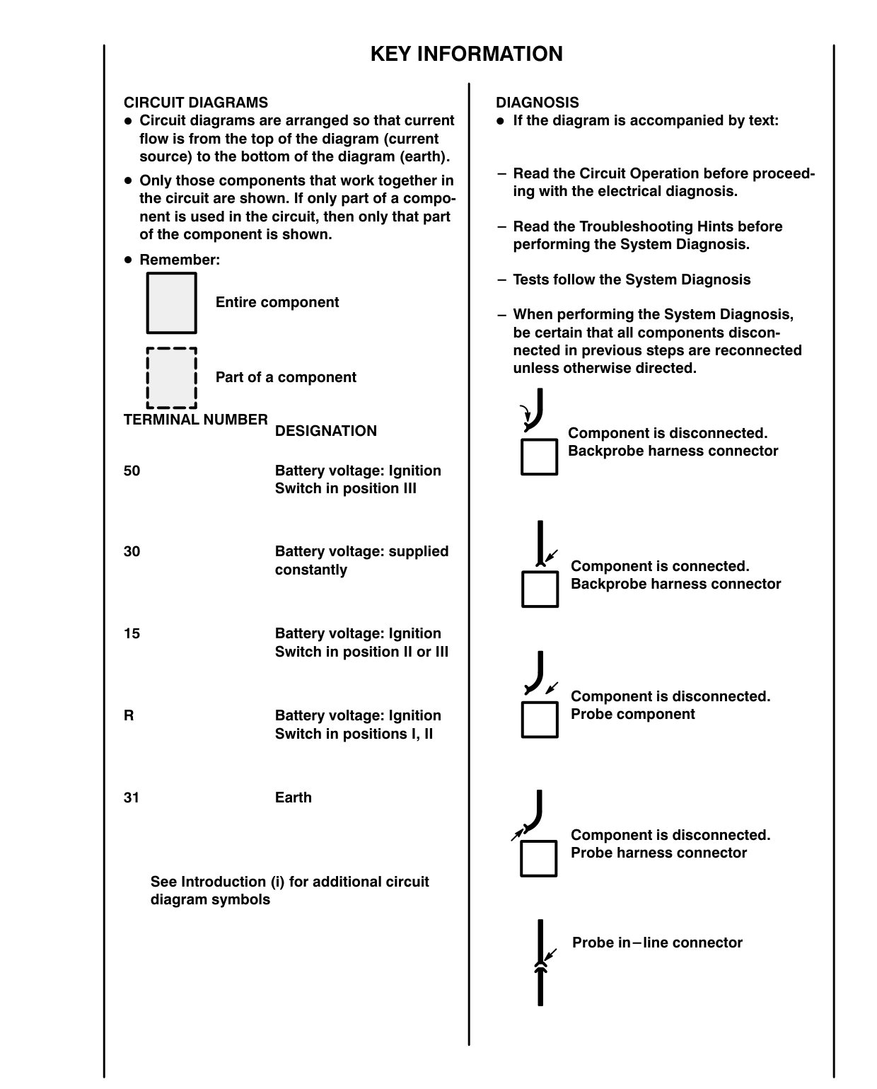
CIRCUIT DIAGRAMS e Circuit diagrams are arranged so that current flow is from the top of the diagram (current source) to the bottom of the diagram (earth). e Only those components that work together in the circuit are shown. If only part of a component is used in the circuit, then only that part of the component is shown.
® Remember:
Entire component
Part of a component | Ll TERMINAL NUMBER DESIGNATION 50 Battery voltage: Ignition Switch in position Ill
30 Battery voltage: supplied constantly
15 Battery voltage: Ignition Switch in position Il or Ili Battery voltage: Ignition Switch in positions I, II
31 Earth See Introduction (i) for additional circuit diagram symbols
DIAGNOSIS [f the diagram is accompanied by text:
- Read the Circuit Operation before proceeding with the electrical diagnosis.
— Read the Troubleshooting Hints before performing the System Diagnosis.
— Tests follow the System Diagnosis
— When performing the System Diagnosis, be certain that all components disconnected in previous steps are reconnected unless otherwise directed.
Component is disconnected. [] Backprobe harness connector
Component is connected. [] Backprobe harness connector
J s Component is disconnected. [] Probe component
Component is disconnected. [] Probe harness connector
| Probe in-line connector
Parts & tools for this job For 1995 Land Rover Range Rover
- TOOLDigital multimeterSearch: automotive digital multimeter
- PARTAssorted fuse kitSearch: car fuse assortment kit
- TOOLWire crimper and connector kitSearch: wire crimper connector kit
Links open Amazon search results in a new tab. As an Amazon Associate I earn from qualifying purchases.