
8.2. Front Disc Brakes (page 2 of 2)
- Make
- Peugeot
- Model
- J5 Pocket Mechanic, 1.8 and 2.0 petrol
- Year
- 1987–1994
- Section
- Front disc brakes
Brake system8.2. Front Disc Brakes · page 2 of 2
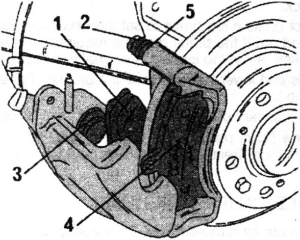
- Inner brake pad
- Guide bolt
- Cylinder dust seal
- Outer brake pad
- Guide bolt rubber seal
- Refer to Figs. 8.3 and 8.4 to remove a brake caliper. Remove the bolt (1) in Fig. 8.3 with a ring spanner, counterholding the guide bolt (2) in Fig. 8.4 with a second ring spanner or open-ended spanner. The guide bolt must not rotate.
- Swing the caliper downwards into the position shown in Fig. 8.4. The brake pad (1) at the inside and the pad (4) at the outside can now be removed from the caliper.
- Insert the inner brake pad (1) and the outer pad (4) in Fig. 8.4. The inner pad has the cable for the pad wear indication and must be routed through the opening "a" in Fig. 8.3.
- Check once more that the pads are fitted correctly and swing the caliper upwards, until the bolt at the top can be fitted. New bolts are normally included in the brake pad repair kit. If none are supplied, coat the threads with "Loctite".
- Hold the guide bolts (2) in Fig. 8.4 with an open-ended spanner and tighten the bolt (1) in Fig. 8.3 to 3.4 kgm (25 ft.lb).
Parts & tools for this job For 1987 Peugeot J5
- PARTFront brake padsSearch: Peugeot J5 1987 front brake pads
- TOOLCaliper piston rewind toolSearch: brake caliper piston rewind tool
- FLUIDBrake fluidSearch: brake fluid
Links open Amazon search results in a new tab. As an Amazon Associate I earn from qualifying purchases.