
8.3.2. wheel brake cylinders
- Make
- Peugeot
- Model
- J5 Pocket Mechanic, 1.8 and 2.0 petrol
- Year
- 1987–1994
- Section
- Rear brakes › 8.3.2. wheel brake cylinders
- Fit the adjuster lever (1). Fig. 8.13 shows more details of the installation. The end “a” of the lever must be placed under the the link (2) and above the pin (3).
- Centre the brake shoes on the brake backplate. Have a last look at the fitted brake shoes by comparing the assembly with Fig. 8.14 to make sure that all parts have been fitted correctly.
- Fit the brake drum and attach with the securing screw and the guide pin for the rear wheel.
- Operate the handbrake and the footbrake a few times to set the self-adjusting mechanism into operation. This will also centre the shoes inside the drum.
- If the wheel brake cylinder has been removed, i.e. the brake pipe disconnected, bleed the brake system as described later on. Remember that each front caliper has two bleed screws.
- Refit the wheels and lower the vehicle to the ground. Tighten the wheel bolts. Treat the brakes with the necessary care for the first few miles.
8.3.2. WHEEL BRAKE CYLINDERS
Before you attempt to overhaul a wheel brake cylinder check if a repair kit is available. You will need some experience with hydraulic cylinders, mainly to evaluate the condition of the cylinder bore and the two pistons. Otherwise it may be better to replace the cylinder.
To dismantle the cylinder, remove the retaining rings from the rubber dust boots at the outside of the cylinder and remove one of the rubber dust caps. The piston is under spring pressure and may “jump” out. Remove the piston and the spring. The rubber cap on the other side can now be removed and the piston withdrawn. The cylinder is now dismantled into the parts shown in Fig. 8.15.
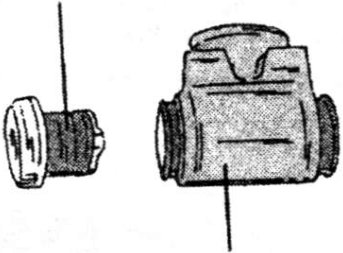
- Piston and dust cap
- Cylinder body
- Return spring
- Piston and rubber cap
Check the fitting direction of the rubber cups on the pistons and remove them, using the fingers only. A small screwdriver can be used to lift a cup until you can get hold of with forefinger and thumb.
Clean all parts thoroughly in white spirit or brake fluid. The cylinder bore must be checked for corrosion, grooves or other blemishes. Very slight indents can be removed with fine-grain sand paper.
Coat the parts with clean brake fluid before assembly. Fit the rubber cups with the sharp edges towards the inside, again using the fingers only. Fit one of the pistons with the rubber dust cap attached into the cylinder bore and fit the cap to the cylinder. Insert the spring and fit the second piston from the other side. Attach both rubber dust caps with the metal band.
Parts & tools for this job For 1987 Peugeot J5
- PARTBrake padsSearch: Peugeot J5 1987 brake pads
- TOOLBrake bleeder kitSearch: one man brake bleeder kit
- FLUIDBrake fluidSearch: brake fluid
Links open Amazon search results in a new tab. As an Amazon Associate I earn from qualifying purchases.