
8.3. Rear Brakes (page 2 of 2)
- Make
- Peugeot
- Model
- J5 Pocket Mechanic, 1.8 and 2.0 petrol
- Year
- 1987–1994
- Section
- Rear brakes
of the brake drum you will see a screw and a guide pin. Remove them to free the drum from the hub. The drum is very tight and three M10 x 1.25 bolts must be screwed into the three bores "a". By tightening the bolts evenly one after the other, the drum should come away. There are, however, cases that you may encounter a sticking drum. This is due to the self-adjusting mechanism inside the brake drum which must be freed. To do this, apply the handbrake and push the plunger (1) in Fig. 8.9 to-
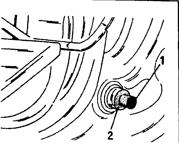
- plunger
- plastic part
the stop for the handbra- ke operating lever inside the brake drum by pul- ling out the plastic part (2). Release the hand- brake and remove the drum.
- Referring to Fig. 8.10 re- move the adjuster lever (1) and the unhook the return spring (2). The upper return spring (4) and the lower spring (3) must be removed with a pair of pliers or use a scsrewdriver and care- fully lift the spring hooks out of their anchorage. The thrust piece (5), i.e. the strut for the self-ad-
justment of the brakes shoes, in the centre will be released and can be taken
out.
- Remove the shoe hold-down springs. Normally a special tool is available, which is used as shown in Fig. 8.11, but a pair of pliers is suitable. Push with a finger from the rear of the backplate against the hold-down pin and rotate the spring seat on the outside with a pair of pliers until the end of the pin can be guided through the slotted hole in the spring seat. Remove the spring seat and the spring and withdraw the pin from the rear.
- Carry out the same operations on the other side of the vehicle.
- Lift the brake shoes off the brake backplate. The handbrake cable must be dis-
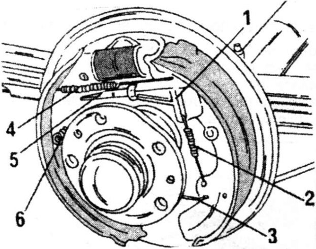
- Adjuster lever
- Adjuster lever spring
- Lower return spring
- Upper return spring
- Adjuster strut
- Shoe hold-down pin
Parts & tools for this job For 1987 Peugeot J5
- PARTBrake padsSearch: Peugeot J5 1987 brake pads
- TOOLBrake bleeder kitSearch: one man brake bleeder kit
- FLUIDBrake fluidSearch: brake fluid
Links open Amazon search results in a new tab. As an Amazon Associate I earn from qualifying purchases.