
Models with air conditioning (page 2 of 2)
- Make
- Rover
- Model
- 200 Workshop Manual
- Year
- 1995–1999
- Section
- Repairs
Manual gearbox - R65Models with air conditioning · page 2 of 2
- Fit bolts securing engine LH mounting to body and tighten to 55 Nm.
- Fit bolts securing engine LH mounting to mounting bracket and tighten to 55 Nm.
- Remove jack and disconnect lifting equipment.
- Connect engine steady bar to bracket on gearbox, fit through bolt and tighten to 45 Nm.
- Tighten through bolt, engine steady bar body, to 85 Nm.
- Fit flywheel front cover plate and tighten bolts to 9 Nm.
- Secure starter motor cable clip to flywheel front cover plate.
- Fit flywheel lower cover plate and tighten bolts to 9 Nm.
- Fit flywheel rear cover plate and tighten bolt to 9 Nm.
- Fit mounting bracket to flywheel housing and secure with bolts.
- Secure clutch cable to clip on mounting bracket.
- Fit LH front tie rod. See FRONT SUSPENSION, Repairs.
- Connect both drive shafts to gearbox, as detailed in Differential oil seal. See this section.
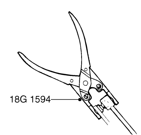
- Using tool 18G 1594 connect gear change linkage ball joint to gear change lever.
- Using tool 18G 1594 connect gear selector linkage ball joint to gear selector lever.
- Models with air conditioning: Align air conditioning pipe to bracket, fit bolt and tighten to 9 Nm.
- Connect multiplug to reverse lamp switch.
- Feed clutch cable through abutment bracket and connect to clutch release lever.
- Position battery tray in vehicle.
- Tighten 3 bolts, battery tray to body, to 10 Nm.
- Position engine compartment fuse box to body, fit bolt and tighten to 10 Nm.
- Fit 4 bolts securing battery tray to body and tighten to 10 Nm.
- Fit and tighten bolt securing engine compartment fuse box to battery tray.
- Fit resonator to air intake pipe.
- Fit and tighten bolts securing resonator to battery tray.
- Fit engine management relay module. See ENGINE MANAGEMENT SYSTEM - MEMS, Repairs.
- Fit ECM. See ENGINE MANAGEMENT SYSTEM - MEMS, Repairs.
- Fit starter motor. See ELECTRICAL, Repairs.
- Fit vehicle speed sensor. See INSTRUMENTS, Repairs.
- Remove stand(s) and lower vehicle.
- Refill gearbox with oil. See Adjustments.
Parts & tools for this job For 1995 Rover 200
- TOOLA/C manifold gauge setSearch: AC manifold gauge set
- TOOLUV leak detection kitSearch: AC UV leak detection kit
- PARTCabin filterSearch: Rover 200 1995 cabin filter
Links open Amazon search results in a new tab. As an Amazon Associate I earn from qualifying purchases.