
47M0055 (page 2 of 8)
- Make
- Rover
- Model
- 600 Rover 600 Repair Manual - Volumes 1 and 2 - 2nd Edition
- Section
- Repairs
Drive shafts47M0055 · page 2 of 8
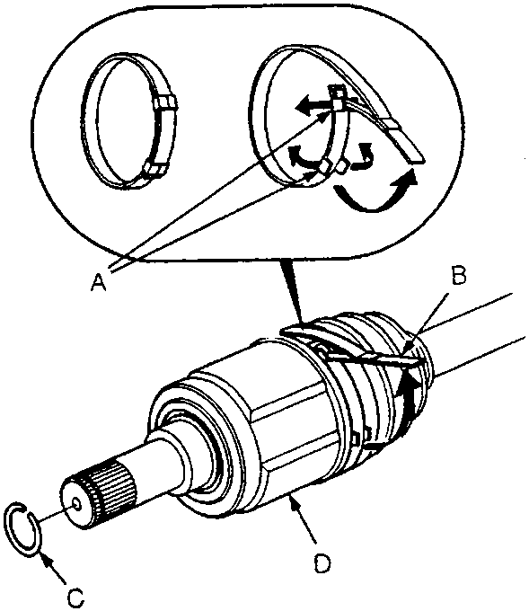
- A Locking Tabs
- B Boot Band
- C Set Ring
- D Inboard Joint
- Remove the set ring from the inboard joint and discard.
- To remove the boot band, pry up the locking tabs with a screwdriver and raise the end of the band.
CAUTION: Take care not to damage the boot.
Note: Carefully clamp the driveshaft in a vice with soft jaws.
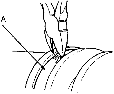
- A Boot Band
- If the boot band is the welded type, cut it off as shown.
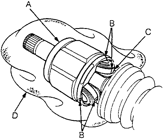
- A Inboard Joint
- B Marks
- C Roller
- D Cloth
- Mark each roller and inboard joint to identify the locations of rollers and grooves in the inboard joint with paint. Then remove the inboard joint on the cloth.
Note: Be careful not to drop the rollers when separating them from the inboard joint.
- Check inboard joint for wear or damage. Check inside bore for wear. Check for cracks.
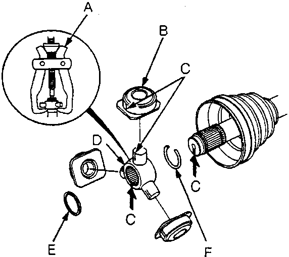
- A Bearing Remover
- B Roller
- C Marks
- D Spider
- E Circlip
- F Stopper Ring
Parts & tools for this job For Rover 600
- PARTWheel bearingSearch: Rover 600 wheel bearing
- TOOLBearing puller kitSearch: wheel bearing puller kit
- PARTCV boot kitSearch: Rover 600 cv boot kit
Links open Amazon search results in a new tab. As an Amazon Associate I earn from qualifying purchases.