
47M0055 (page 3 of 8)
- Make
- Rover
- Model
- 600 Rover 600 Repair Manual - Volumes 1 and 2 - 2nd Edition
- Section
- Repairs
Drive shafts47M0055 · page 3 of 8
- Mark the rollers and spider to identify the locations of rollers on the spider. Then remove the rollers.
- Remove the circlip.
- Mark the spider and driveshaft to identify the position of the spider on the shaft.
- Remove the spider using a commercially available bearing remover.
- Remove the stopper ring.
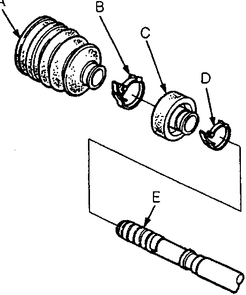
A Inboard Boot
B Boot Band
C Dynamic Damper
D Dynamic Damper Band
E Vinyl Tape
- Wrap the splines on the driveshaft with vinyl tape to prevent damage to the inboard boot and dynamic damper.
- Remove the boot band and inboard boot. Check the boot for cracks, splitting and wear and replace the boot bands.
CAUTION: Take care not to damage the boot. - Remove the dynamic damper band and dynamic damper, if equipped. Replace the band and inspect the damper for damage.
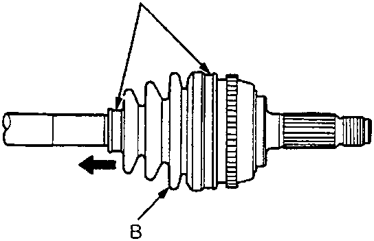
A Boot Bands
B Outboard Boot
- Remove the outboard boot bands, then slide the outboard boot to the inboard joint side. Check the boot for cracks, splitting and wear and replace the boot bands.
CAUTION: Take care not to damage the boot. - Wipe off the grease to expose the driveshaft and the outboard joint inner race.
- Mark the driveshaft at the same position of the inner race end with paint.
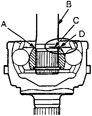
A Outboard Joint Inner Race
B Driveshaft
C Paint Mark
D Inner Race End
Parts & tools for this job For Rover 600
- PARTWheel bearingSearch: Rover 600 wheel bearing
- TOOLBearing puller kitSearch: wheel bearing puller kit
- PARTCV boot kitSearch: Rover 600 cv boot kit
Links open Amazon search results in a new tab. As an Amazon Associate I earn from qualifying purchases.