
Caution: (page 2 of 5)
- Make
- Rover
- Model
- 600 Rover 600 Repair Manual - Volumes 1 and 2 - 2nd Edition
- Section
- Information
Heating and ventilationCaution: · page 2 of 5
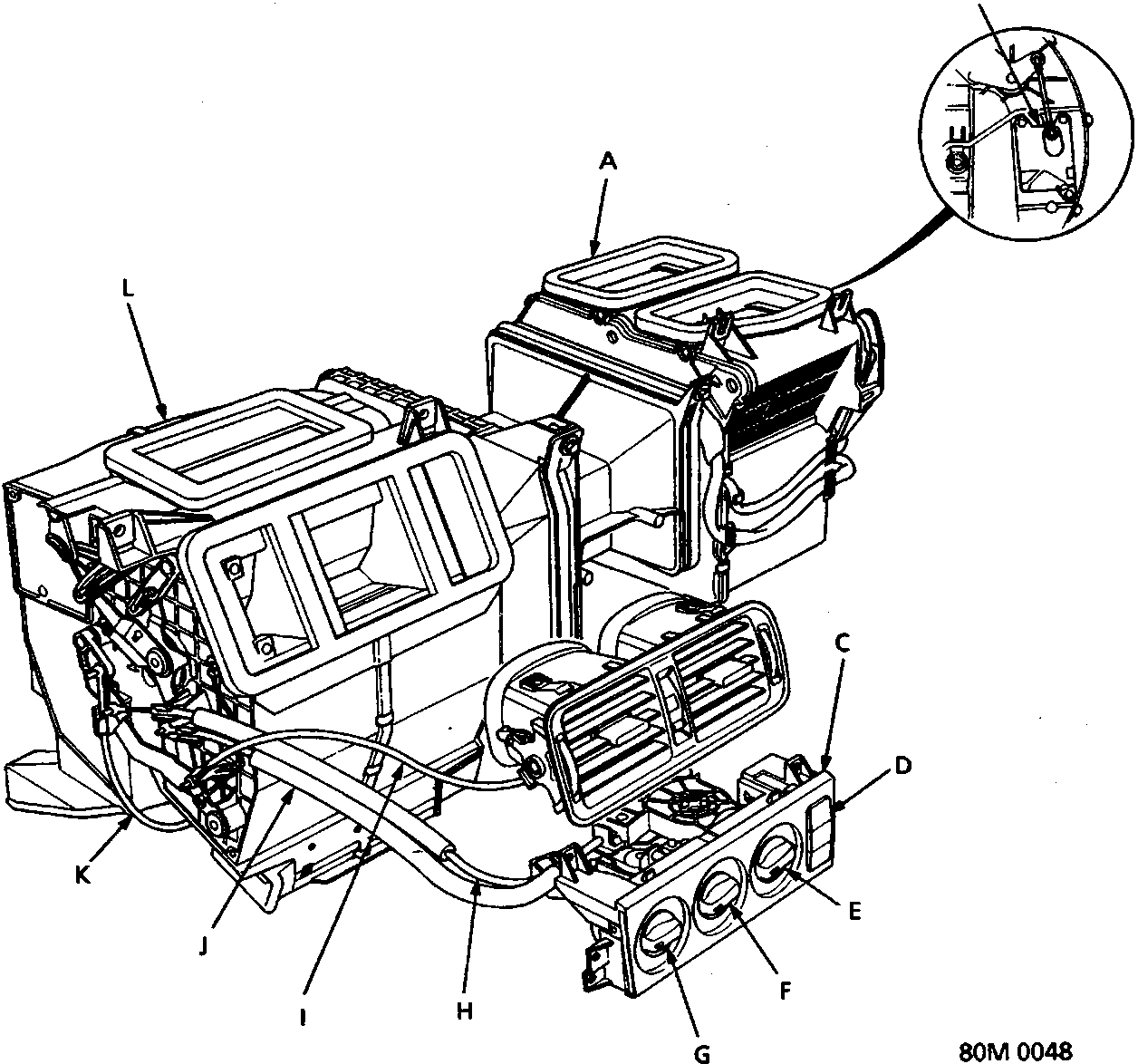
| A Blower unit | G Heater fan switch |
| B Recirculation control motor | H Air mix control cable |
| C Heater control panel | I Cool vent cable |
| D Recirculation control switch | J Mode control cable |
| E Mode control knob | K Heater valve cable |
| F Temperature control knob | L Heater unit |
Parts & tools for this job For Rover 600
- TOOLA/C manifold gauge setSearch: AC manifold gauge set
- TOOLUV leak detection kitSearch: AC UV leak detection kit
- PARTCabin filterSearch: Rover 600 cabin filter
Links open Amazon search results in a new tab. As an Amazon Associate I earn from qualifying purchases.