
Symptom Chart (page 2 of 3)
- Make
- Rover
- Model
- 600 Rover 600 Repair Manual - Volumes 1 and 2 - 2nd Edition
- Section
- Information
Heating and ventilationSymptom Chart · page 2 of 3
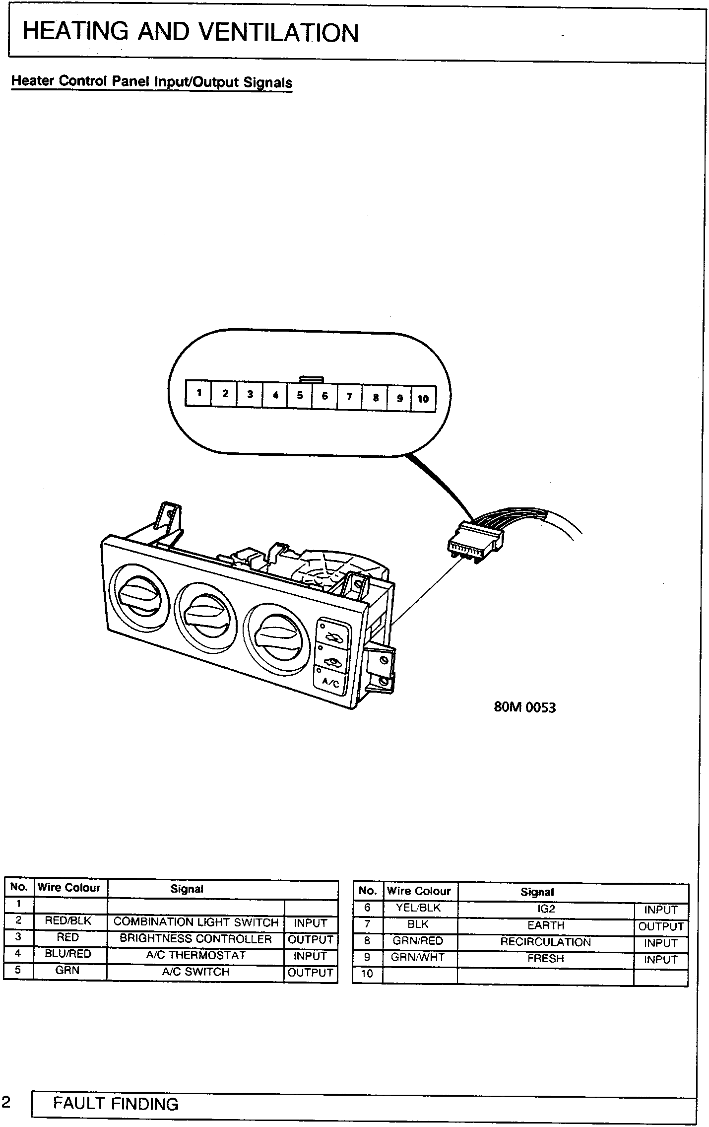
| No. | Wire Colour | Signal | |
|---|---|---|---|
| 1 | |||
| 2 | RED/BLK | COMBINATION LIGHT SWITCH | INPUT |
| 3 | RED | BRIGHTNESS CONTROLLER | OUTPUT |
| 4 | BLU/RED | A/C THERMOSTAT | INPUT |
| 5 | GRN | A/C SWITCH | OUTPUT |
| No. | Wire Colour | Signal | |
|---|---|---|---|
| 6 | YEL/BLK | IG2 | INPUT |
| 7 | BLK | EARTH | OUTPUT |
| 8 | GRN/RED | RECIRCULATION | INPUT |
| 9 | GRN/WHT | FRESH | INPUT |
| 10 | |||
Parts & tools for this job For Rover 600
- TOOLA/C manifold gauge setSearch: AC manifold gauge set
- TOOLUV leak detection kitSearch: AC UV leak detection kit
- PARTCabin filterSearch: Rover 600 cabin filter
Links open Amazon search results in a new tab. As an Amazon Associate I earn from qualifying purchases.