
Coolant pump housing (page 2 of 2)
- Make
- Rover
- Model
- 600 620 Diesel Repair Manual Supplement
- Year
- 1995–1999
- Section
- Repairs
Cooling systemCoolant pump housing · page 2 of 2
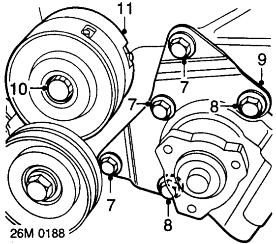
- Noting their fitted position, remove 3 bolts securing support bracket to power steering pump and coolant pump housing.
- Remove 2 long bolts securing steering pump to coolant pump housing.
- Release steering pump from coolant pump housing and position aside.
- Remove bolt securing drive belt tensioner to coolant pump housing.
- Remove drive belt tensioner assembly.
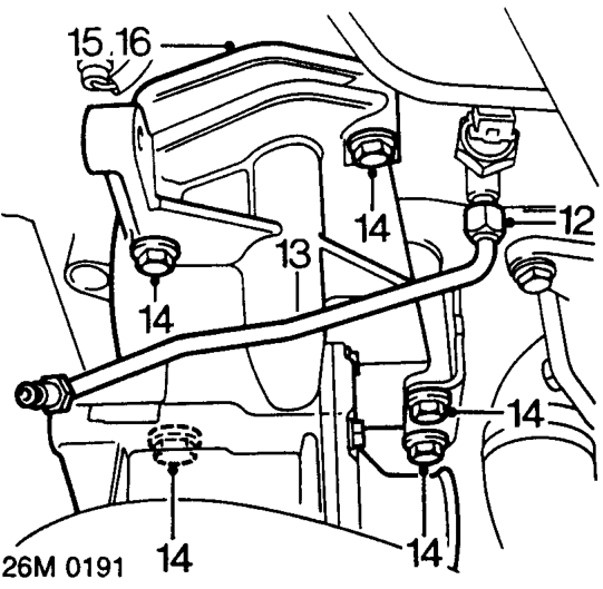
- Slacken union securing vacuum pump oil feed pipe to oil pressure sensor.
- Disconnect and remove oil feed pipe.
- Remove 5 bolts securing coolant pump housing to cylinder block.
- Release and remove coolant pump housing.
- Remove and discard ’O’ ring seal from rear of coolant pump housing.
Do not carry out further dismantling if component is removed for access only.
- Remove 4 bolts securing coolant pump cover to housing and remove cover.
- Remove coolant pump from housing.
- Remove and discard 3 ’O’ ring seals from coolant pump.
- Clean mating faces of coolant pump, coolant pump cover and coolant pump housing.
- Clean ’O’ ring seal grooves and bolt holes in coolant pump housing.
- Apply Loctite 405 to ’O’ ring seal grooves and fit new ’O’ ring seals.
- Fit coolant pump and cover to coolant pump housing.
- Fit 4 bolts and tighten to 45 Nm.
Parts & tools for this job For 1995 Rover 600
- FLUIDCoolantSearch: Rover coolant antifreeze
- PARTThermostatSearch: Rover 600 1995 thermostat
- TOOLCooling system pressure testerSearch: cooling system pressure tester
Links open Amazon search results in a new tab. As an Amazon Associate I earn from qualifying purchases.