Workshop Manuals Factory service & repair Rover
01 General information02 Information03 Maintenance04 Engine 1.4 K805 Engine 1.606 Engine 1.6 D.O.H.C.07 Engine 2.0 T1608 Engine management system - PGM-Fi09 Modular engine management system - SPi10 Modular engine management system - MPi11 Fuel delivery system12 Cooling system13 Manifold and exhaust14 Clutch15 Manual gearbox 1.416 Manual gearbox 1.617 Automatic gearbox18 Drive shafts19 Steering20 Suspension21 Brakes22 Body23 Heating and ventilation24 Air conditioning25 Wipers and washers26 Electrical27 Instruments28 Supplementary restraint system (SRS)
Rover 200/400 Coupé, Cabriolet & Tourer Workshop Manual21 · Brakes
21 · Brakes

Brakes: Description and operation (page 5 of 8)

Make
Rover
Model
Coupé, Cabriolet & Tourer 200/400 Coupé, Cabriolet & Tourer Workshop Manual
Section
Description and operation
BrakesDescription and operation · page 5 of 8

Brakes: Description and operation (page 5 of 8) – diagram from the Brakes chapter of the Rover 200/400 Coupé, Cabriolet & Tourer Workshop Manual factory manual.

Vertical split panel for refrigerator door hinge installation
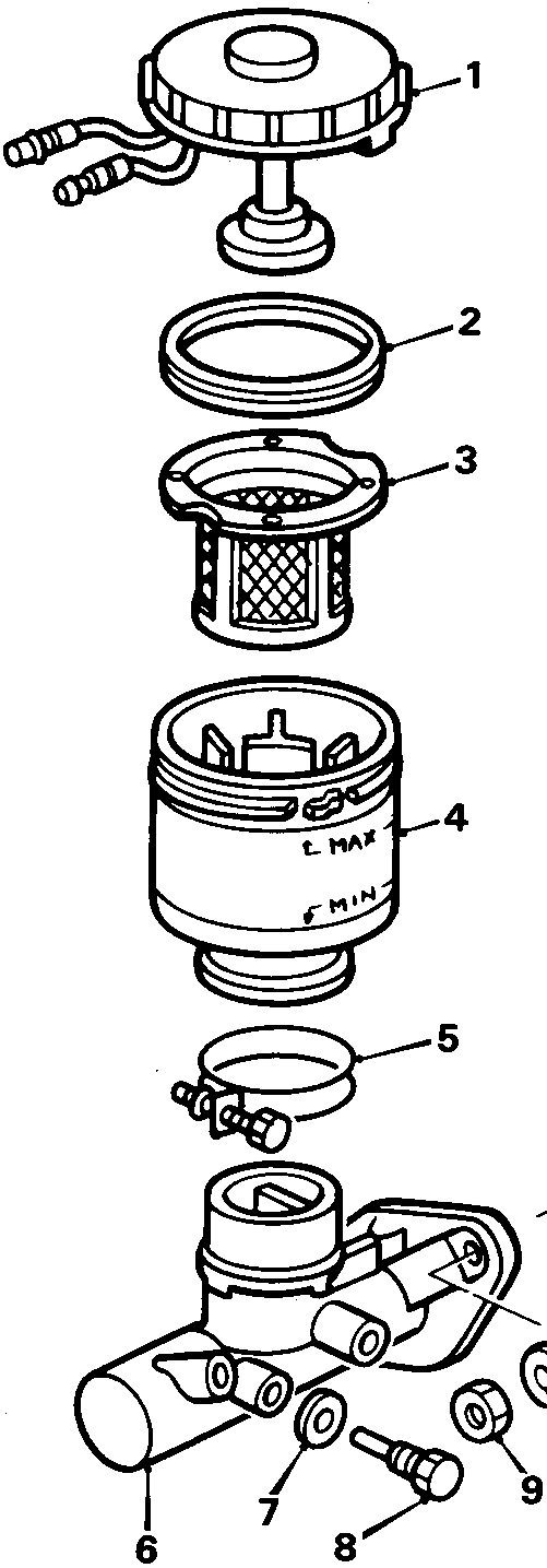
Exploded view of a brake fluid reservoir assembly showing the cap, filter, reservoir body, and mounting hardware with callout numbers 1 through 10.
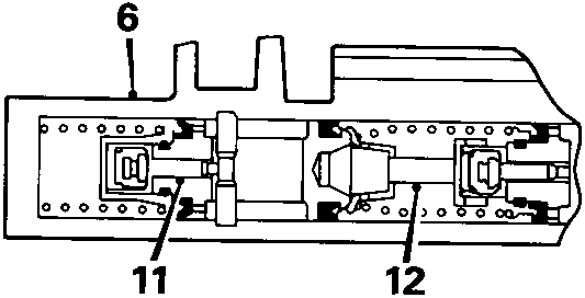
Cross-sectional diagram of a hydraulic valve unit showing internal components labeled 6, 11, and 12.
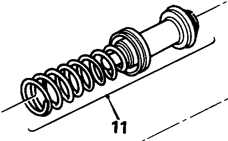
Close-up exploded view of a spring-loaded piston assembly labeled 11.
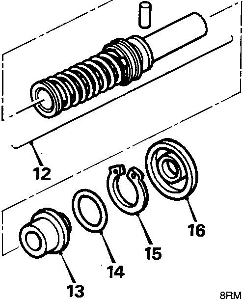
Close-up exploded view of a spring-loaded piston assembly labeled 12, along with associated seals and retainers labeled 13 through 16.

8RM 0412 A

Parts & tools for this job For Rover Coupé, Cabriolet & Tourer

Links open Amazon search results in a new tab. As an Amazon Associate I earn from qualifying purchases.