
Engine – Function
- Make
- Volvo
- Model
- XC90 Factory Service Manual
- Year
- 2003–2016
- Section
- 09 Miscellaneous › Design and Function › Engine – Function
Engine – Function
Crankshaft movement
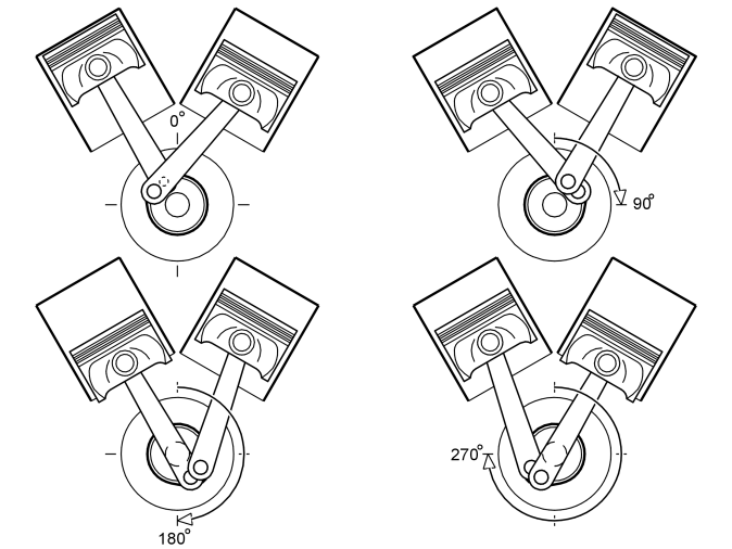
To achieve an even running and characteristic V8 sound, the ignition impulse interval is 90 crankshaft degrees. To reach this in an engine with a 60 degree angle between the cylinder banks, the crankshaft pins for the opposing cylinder pairs are offset by 30 degrees.
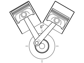
When the left hand piston is at the top, the right hand piston is halfway between the upper and lower turn points. This is because the crankshaft pins are internally offset by 30 degrees.
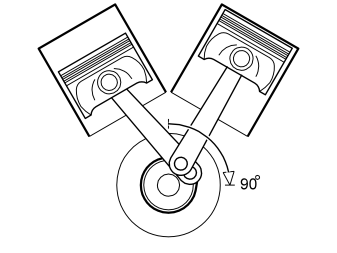
When the crankshaft has rotated 90 degrees the right hand piston is at the top and the left hand piston is halfway between the upper and lower turning points.
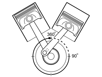
When the crankshaft has rotated a further 270 degrees the left hand piston is at the top and the right hand piston is halfway between the upper and lower turning points.
By offsetting the crankshaft pins by 30 degrees in this way the ignition impulses will occur every 90th crankshaft degree.
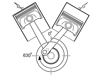
The Example shows the principle for cylinder 1 and 2. With the firing order 1-8-4-3-6-5-7-2 the following occurs:
- Cylinder 1 fires.
- The crankshaft then rotates 360°+270°=630° until cylinder 2 fires.
- The next ignition impulse, now again for cylinder 1, occurs when the crankshaft has rotated a further 90 degrees.
Lubrication system
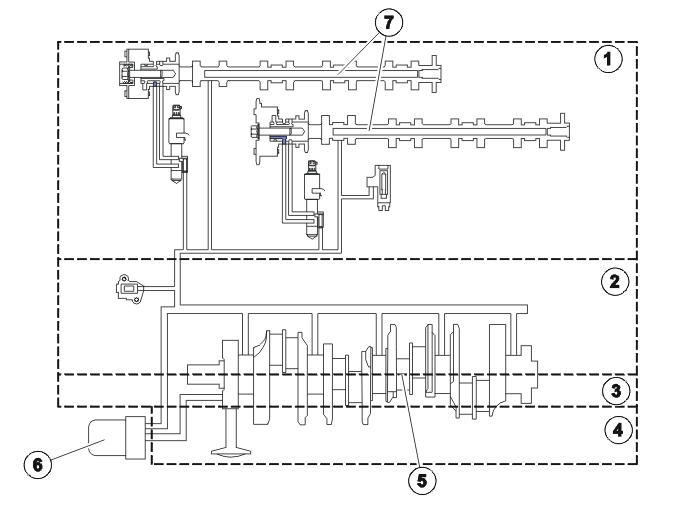
- Cylinder head
- Cylinder block
- Intermediate section
- Oil sump
- Crankshaft
- Oil filter
- Camshafts
Oil is led from the oil sump via a suction nozzle to the oil pump, which is located on the crankshaft. The oil pump suction function is facilitated by a purge valve that eliminates any air from the system.
The oil is pumped on to the oil cooler system and then on to the oil filter. The oil is led from the filter through a cast oil duct in the intermediate section to the main bearings. The oil is distributed to the big-end bearings via drilled channels in the crankshaft.
The camshafts receive their oil supply via drilled channels in the cylinder block. The channels continue up through the cylinder heads where they open out on the underside of the lower half of the cylinder head. There is a cross channel in the channels to the cylinder heads which leads oil to the pistons. From here the oil is moved further via the oil channels to the intake camshaft bearings and valve lifters.
The exhaust camshaft bearings are supplied via two cast cross channels at the front of the upper halves. The oil is led via drains in the block from the cylinder heads and from the crankshaft bearings back to the oil pan.
Crankcase ventilation
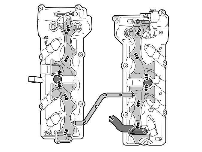
The system is pressure controlled and completely enclosed.
Crankcase gases flow up to both the valve covers. There is a hose connecting the valve covers. A labyrinth system of plates is installed in the valve covers. The oil in the gases condenses on the plates and drains back to the oil pan.
The ventilation is pressure controlled to retain stable pressure in the crankcase. A pressure regulator is installed on the rear edge of the right valve cover. The gases which are evacuated are led from the regulator through a hose to a connection on the inlet pipe. Coolant is circulated around the connection to prevent freezing.
The pressure in the crankcase is approximately - 0.03 bar.
Cooling system
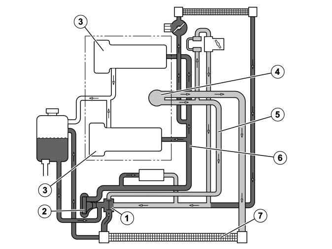
The combustion of fuel in the vehicle engine produces both mechanical motion and excess energy. The excess energy takes the form of heat that is led away from the engine via:
- exhaust gases
- convection to the air in the engine compartment
- transfer to the coolant in the cooling system
- the engine oil.
The thermostat (1) regulates the amount of coolant to the engine. The wax body in the thermostat expands when subjected to heat.
The coolant is pumped by the coolant pump (2) to the inlets (6) for the cylinder heads (3). The coolant flows forward through the relevant cylinder head and on through the cylinder banks back to the common outlet (4). After passing the engine the coolant flows by:
- Closed thermostat through the bypass pipe (5) back to the coolant pump without cooling off.
- Open thermostat through the radiator (7) to the coolant pump. The coolant also flows through the bypass pipe back to the coolant pump.
Exhaust system
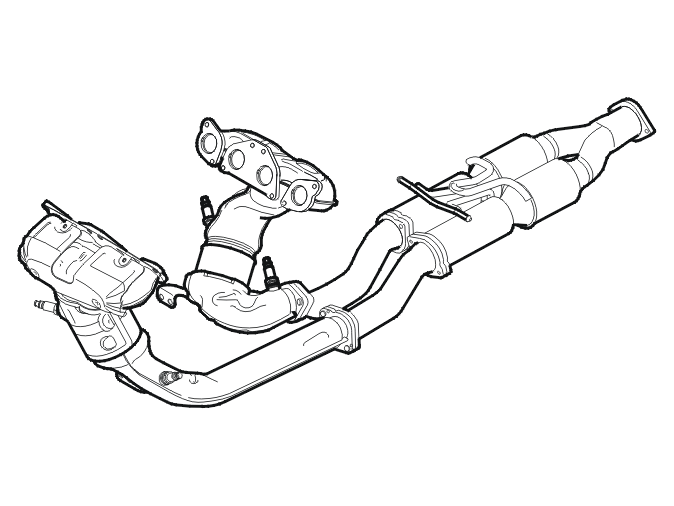
Hint: The illustration displays the exhaust system for the XC90.
The three-way catalytic converters clean by oxidizing carbon monoxide (CO) and hydrocarbons (HC) to water and carbon dioxide (CO2). Nitrous oxides (NOx) are reduced to nitrogen and water. The catalytic converter transforms over 98 percent of these substances during normal operation. Lead contaminates in the fuel can damage the catalytic converter, quickly rendering it inoperable.
Parts & tools for this job For 2003 Volvo XC90
- PARTEngine gasket setSearch: Volvo XC90 2003 engine gasket set
- TOOLTorque wrenchSearch: 3/8 inch torque wrench
- TOOLFeeler gauge setSearch: feeler gauge set
Links open Amazon search results in a new tab. As an Amazon Associate I earn from qualifying purchases.