
Checking Components
- Make
- Alfa Romeo
- Model
- 145/146 Electrical System Diagnosis Manual, Volume 3
- Year
- 1994–2001
- Section
- Power Supply › Checking Components
146 electrical system diagnosisChecking Components
Checking Components
Branch terminal box G56 (except T.SPARK and JTD)
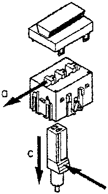
Removing a connector
- move the "secondary-lock" to the left
- press the release catch of the connector to be removed
- remove the connector pulling downwards
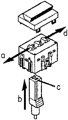
Inserting a connector
- position the "secondary-lock" at the left
- insert the connector
- press the connector until it catches in the tooth
- move the "secondary-lock" to the right
General supply fuse G393 (except T.SPARK and JTD)
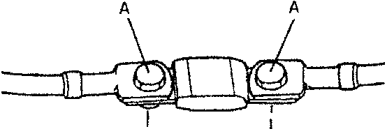
"MEGA" general supply protection fuse: (150A).
In the event of replacement tighten the two fastening screws (A), proceeding with care, to a torque of apr. 25 Nm, without forcing the fuse excessively to avoid damaging the copper element.
Parts & tools for this job For 1994 Alfa Romeo 145/146
- TOOLDigital multimeterSearch: automotive digital multimeter
- PARTAssorted fuse kitSearch: car fuse assortment kit
- TOOLWire crimper and connector kitSearch: wire crimper connector kit
Links open Amazon search results in a new tab. As an Amazon Associate I earn from qualifying purchases.