
FUNCTIONAL DESCRIPTION (JTD version)
- Make
- Alfa Romeo
- Model
- 145/146 Electrical System Diagnosis Manual, Volume 3
- Year
- 1994–2001
- Section
- Power Supply › FUNCTIONAL DESCRIPTION (JTD version)
FUNCTIONAL DESCRIPTION (JTD version)
The supply leading from the battery A1 is subdivided into various lines in the branch terminal box G56. This is a branch terminal box with built-in fuses, which makes it possible to protect all the supply lines except the starter motor cable (battery-starter motor) and the battery charging cable (starter motor-alternator); these cables are however protected by an additional "reinforced" sheath.
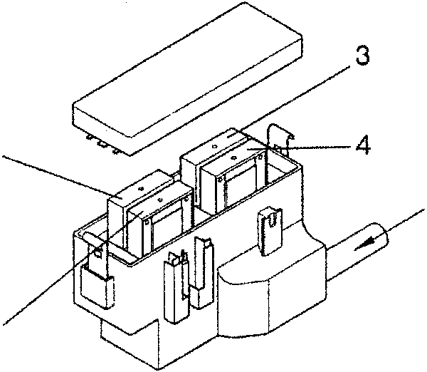
b. line (16 mm cable) from the battery
- Fan fuse (50A): G254
- Services supply fuse (30A): G384
- General supply fuse (60A): G393a
- General supply fuse (60A): G393b
From this, lead the cables which directly supply certain systems and the line that supplies the fusebox G1; inside the fusebox the supply is branched to the various circuits, protected by the corresponding fuses (see "Fusebox" section).
The battery charging line leads from the alternator A3, via the starter motor A11.
The ignition switch B1 is also supplied via the branch terminal box G56 and the specific fuse G384 at pin B of connector B.
The line that leaves pin A of connector B is the one corresponding to the "STASRT" position and directly supplies the starter motor A11.
The line that leaves pin 3 of connector A - "DRIVE" position - supplies, via the fusebox G1, the "key-operated" circuits which are disengaged in the "START" position.
The lines that leave pin 1 of connector A and pin C of connector B supply, either directly or via the fusebox G1, the "key-operated" circuits which also remain engaged in the "START" position.
Pin C of connector B is not connected.
Lastly the line leaving pin 2 of connector A corresponds to the "PARK" position and supplies the side-lights circuit inside the fusebox G1.
Parts & tools for this job For 1994 Alfa Romeo 145/146
- TOOLDigital multimeterSearch: automotive digital multimeter
- PARTAssorted fuse kitSearch: car fuse assortment kit
- TOOLWire crimper and connector kitSearch: wire crimper connector kit
Links open Amazon search results in a new tab. As an Amazon Associate I earn from qualifying purchases.