
Changing the flywheel ring gear
- Make
- Alfa Romeo
- Model
- 145/146 Engines, 146 Bodywork and Engine Overhaul Manual
- Year
- 1994–2001
- Section
- Overhauling › Changing the flywheel ring gear
‹ Prev Checking and differences in weight between single pistons and single connecting rodsNext › Instructions for reassembly
Engine overhaul: 1.9 TD (AR67501)Changing the flywheel ring gear
- Measure the diameter of the hole on the piston paired with the gudgeon pins and check that it is within the specified limits.
| Gudgeon pin hole diameter in pistons | ||
|---|---|---|
| Version before change | Class 1 | 25.993 ÷ 25.996 mm |
| Class 2 | 25.996 ÷ 25.999 mm | |
| Version after change | 25.994 ÷ 25.999 mm | |
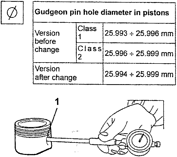
- Calculate the clearance between the gudgeon pins and their seats on the pistons and check that it is within the specified limits.
| Clearance between gudgeon pins and seats on pistons | |
|---|---|
| Version before change | 0.003 ÷ 0.009 mm |
| Version after change | 0.003 ÷ 0.012 mm |
Changing the flywheel ring gear
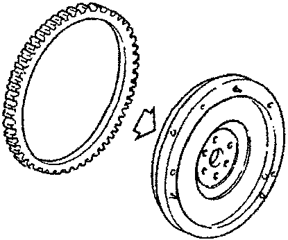
- Check that the flywheel ring gear is intact and, if necessary, replace it proceeding as follows:
- remove the old ring gear using a hydraulic press.
- carefully clean the contact surfaces of the new ring gear and of the flywheel.
- evenly heat the new ring gear to a temperature of 80 °C and fit it on the flywheel.
- allow to cool in a natural environment; do not force cool.
Inspecting and checking the oil pump
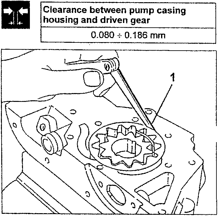
- Check that the clearance between the pump casing housing and the driven gear is within the specified limit.
| Clearance between pump casing housing and driven gear | |
|---|---|
| 0.080 ÷ 0.186 mm |
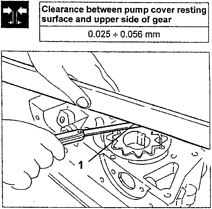
- Check that the clearance between the resting surface of the pump cover and the upper side of the gears is within the specified limit.
WARNING: If the clearances are not within the specified limits, change the front cover with incorporated oil pump.
| Clearance between pump cover resting surface and upper side of gear | |
|---|---|
| 0.025 ÷ 0.056 mm |

‹ Prev Checking and differences in weight between single pistons and single connecting rodsNext › Instructions for reassembly
Parts & tools for this job For 1994 Alfa Romeo 145/146
- PARTEngine gasket setSearch: Alfa Romeo 145/146 1994 engine gasket set
- TOOLTorque wrenchSearch: 3/8 inch torque wrench
- TOOLFeeler gauge setSearch: feeler gauge set
Links open Amazon search results in a new tab. As an Amazon Associate I earn from qualifying purchases.