
b. Alignment of electrodes.
- Make
- Alfa Romeo
- Model
- 145/146 Factory Service Manual
- Year
- 1994–1999
- Section
- Body - Generalities › b. Alignment of electrodes.
‹ Prev Protection of external components and furnishingsNext › Indications to be followed when spot welding.
Bodyworkb. Alignment of electrodes.
b. Alignment of electrodes.
- Align the tips of the upper and lower electrodes. Any misalignment of the electrodes causes low pressure on the welding points resulting in a reduction in strength.
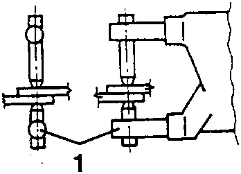
- Correct alignment of arms
- Incorrect position of arms
- Incorrect length of arms
c. Diameter of electrode tip
- It is necessary to check the diameter of the electrode in order to obtain the necessary welding strength. Before beginning work ensure that the diameter of the tip (D) is adequate for the thickness of the metal sheet following the formula given. Remove II traces of burns or foreign bodies from the tips of the electrodes.
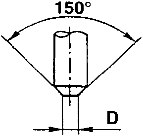
D = t + 3 (mm) D = Diameter of the electrode tip
t = Thickness of sheet metal
Condition and preparation of the panels to be welded.
The presence of discontinuity, paint, rust or dust on panel edges prevents the flow of electricity and thus reduces welding strength. Before beginning welding check the condition of the mating surfaces and make any adjustments necessary.
a. Gaps between mating surfaces
- Even a slight gap between the surfaces to be welded reduces the intensity of the flow of electricity resulting in welds which will be too small or weak. Before welding join the surfaces and when necessary, secure them with a clamp.
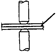
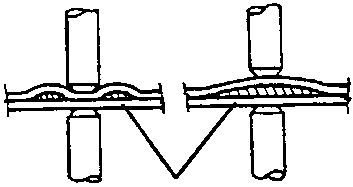
- Correct mating of the surfaces to be welded
- Incorrect mating - gap between the surfaces to be welded
b. Welding of metal surfaces.
- To obtain the best results prepare the surfaces to be welded by removing all traces of impurities and foreign bodies (paint, dust, rust).
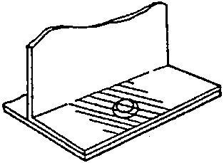
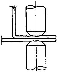
c. Corrosion prevention on metal surfaces.
- Coat the area to be welded with a high conductive corrosion inhibitor. The edges should also be coated with this product.
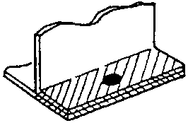
APPLY THE CORROSION INHIBITOR TO ALL THE SURFACES AND AROUND THE EDGES
PRELIMINARY OPERATIONS
‹ Prev Protection of external components and furnishingsNext › Indications to be followed when spot welding.
Parts & tools for this job For 1994 Alfa Romeo 145/146
- TOOLTie rod end toolSearch: tie rod end puller
- TOOLBall joint separatorSearch: ball joint separator
- FLUIDPower steering fluidSearch: Alfa Romeo power steering fluid
Links open Amazon search results in a new tab. As an Amazon Associate I earn from qualifying purchases.