
The casing
- Make
- Alfa Romeo
- Model
- 147 Factory Service Manual
- Year
- 2000–2002
- Section
- Warning and manoeuvring indicators › The casing
THE CASING
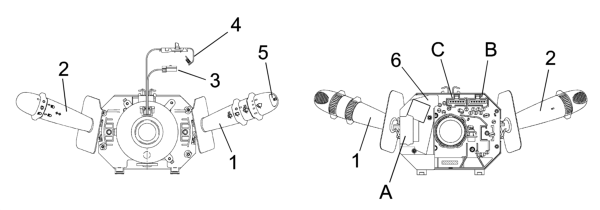
- 1 Right lever with front/rear wiper controls
- 2 Left lever with lighting/direction indicator controls
- 3 Horn/radio controls cable
- 4 Air Bag clock spring
- 5 Trip computer control button
- 6 Internal electronic module
- ABC - Connectors
It is a part of the steering column switch unit containing the electrical circuits and the switching and automatic release mechanisms which return the left lever to the rest position once the steering wheel has been realigned. Attachment angle 80° ±
5° release angle 60° ± 5°.
The front part of the CASING houses the CLOCK SPRING which provides the interface with the steering wheel.
At the rear is the collar with a retaining band for fastening it to the steering column and additional attachments which guarantee the axial and angular position of the steering column switch unit on the steering column.
The steering column switch unit casing contains the fastenings for the upper and lower half casings.
The ELECTRONIC MODULE is connected to the CASING.
The rear of the CASING contains the housings for the electrical connectors.
Parts & tools for this job For 2000 Alfa Romeo 147
- TOOLDigital multimeterSearch: automotive digital multimeter
- PARTAssorted fuse kitSearch: car fuse assortment kit
- TOOLWire crimper and connector kitSearch: wire crimper connector kit
Links open Amazon search results in a new tab. As an Amazon Associate I earn from qualifying purchases.