
E3510 Car radio
- Make
- Alfa Romeo
- Model
- 147 Factory Service Manual
- Year
- 2000–2002
- Section
- Radio accessories › E3510 Car radio
E3510 Car radio
Description
A sophisticated 'Bose' HI FI system with special speakers and an outside amplifier is available on request.
The system has been developed ad hoc for the vehicle: the acoustic properties of the passenger compartment have been carefully designed so that the amplifier and the speakers are perfectly suited to the vehicle: the sound is excellent throughout the passenger compartment.
Unlike the system fitted as standard, the Bose system includes:
- coaxial loudspeakers in the front doors (with incorporated tweeters)
- coaxial rear loudspeakers (with incorporated tweeters) on the rear side panel;
- rear subwoofer loudspeaker;
- BOSE amplifier, located in the boot compartment on the left.
The other componetns are the same as for the radio system:
- radio (various versions are available)
- radio supply cables
- leads connecting the radio to the speakers;
- fishpole antenna with base mounted on the rear of the roof, coaxial cable and supply cable for aerial amplifier.
For everything concerning the basic system, Wiring diagram E3510 CAR RADIO .
For more details Characteristic of working principle 5570 Accessories .
Description of operation
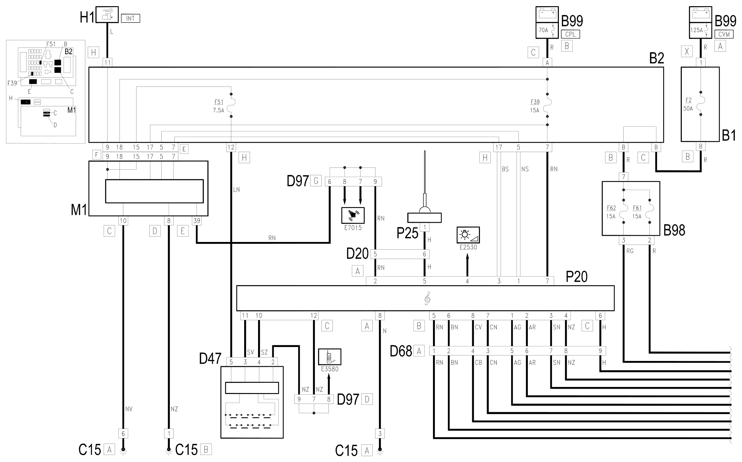
The radio P20 is supplied directly (7 of connector A) from the battery via the line of fuse F39 of the unit under the dashboard B2 and the CPL maxifuse of B99. Another specific supply reaches pin 2 of connector A, to indicate the presence of the Bose Hi Fi system.
The supply to side lights on Wiring diagram E2530 INSTRUMENT LIGHTING reaches pin 4 of connector A.
Pins 1 and 3 of connector A receive the CAN line with which the radio P20 is connected to the Body Computer M1 and the other nodes of the system.
Pin 8 of connector A is earthed.
The aerial P25 is supplied from pin 5 of connector A. The aerial is connected to the radio also via the specific coaxial cable.
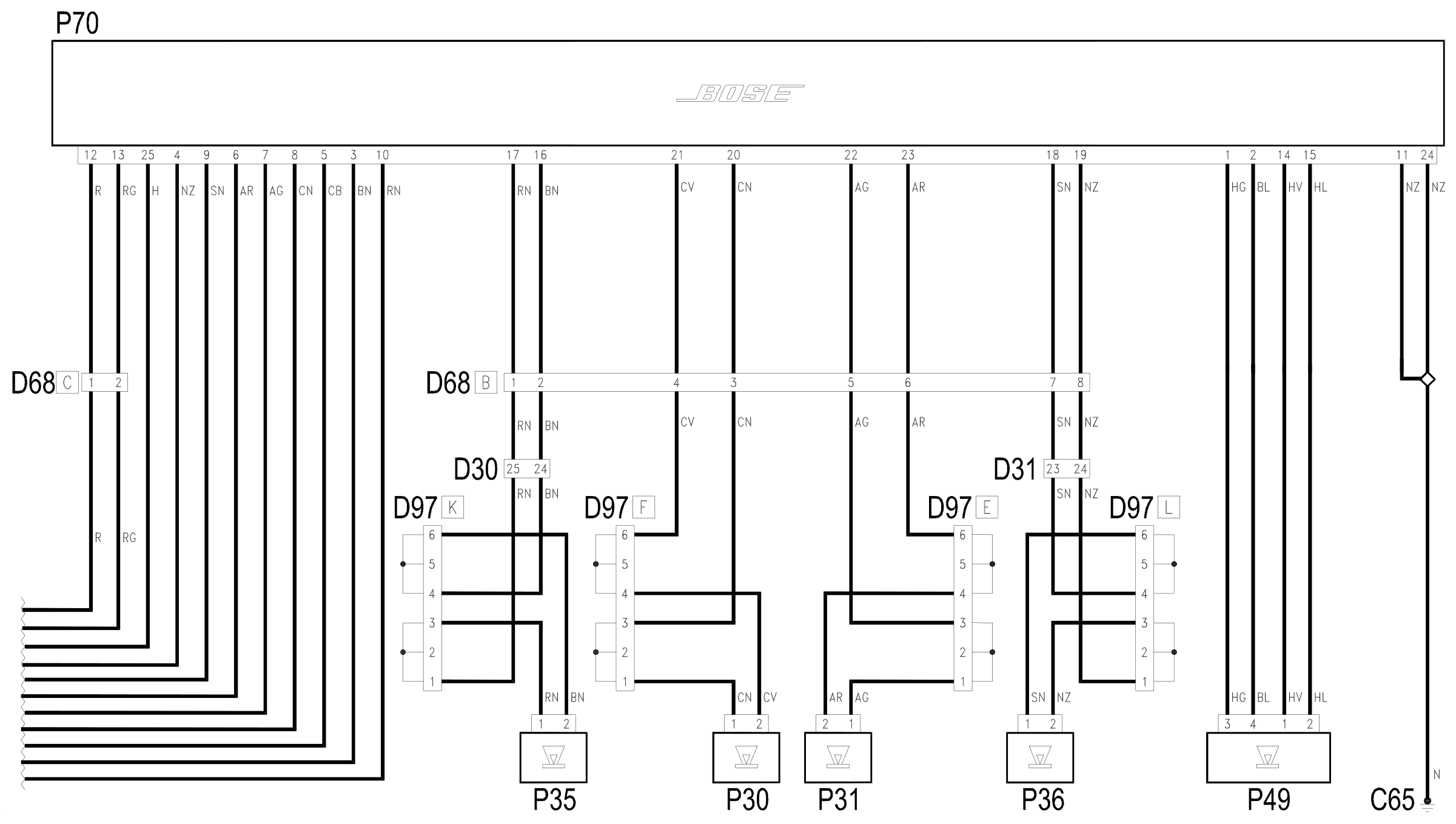
The cables with the signals to the loudspeakers com out of connector B; these signals are sent to the amplifier BOSE P70, which controls the loudspeakers:
- pins 5 and 6 to the left front loudspeaker P35,
- pins 3 and 4 to the right front loudspeaker P36,
- pins 7 and 8 to the left rear loudspeaker P30,
- pins 1 and 2 to the right rear loudspeaker P31,
Pins 10 and 11 of connector C connect to the radio controls on the steering wheel: the connection takes place via the clock spring D47; the device which controls the control buttons receives a supply controlled by the ignition (INT) from the line protected by fuse F51 of the unit under the dashboard B2, while the reference earth arrives from pin 12 of connector C of P20.
The amplifier P70 is supplied directly from the battery - to pins 12 and 13 via the line of fuse F1 of B1 and the specific fuses F61 and F62 of the additional fusebox B98.
It is then connected - pin 25 - with a specific line to the radio P20 - pin 6 of connector C - which sends the signal to switch on the amplifier.
Pins 11 and 24 to earth.
The other signals coming from the BOSE amplifier P70 control, as described above, the loudspeakers of the basic system. In addition, the signals which control the rear subwoofer P49 emerge from pins 1-2 and 14-15.
Wiring diagram
Components
| Code | Component | See |
|---|---|---|
| B01 | Engine compartment junction unit | description 5505A |
| B02 | Junction unit under dashboard | description 5505A |
| B98 | Supplementary fuse box | |
| B99 | Maxifuse box on battery | description 5530B |
| C15 | Facia earth, driver's side | |
| C65 | Bose system earth | |
| D20 | /Rear dashboard coupling | |
| D30 | Rear coupling for /front door. driver's side | |
| D31 | /Front passenger door. rear coupling | |
| D41 | Rear dashboard/ coupling for speakers | |
| D47 | Clock spring coupling | description 5580C |
| D68 | Bose system coupling | |
| D97 | Short circuiting coupling | |
| H01 | Ignition switch | description 5520A |
| M01 | Body computer | description 5505A |
| P20 | Car radio | |
| P25 | Aerial amplifier / feeder | |
| P30 | Left rear speaker | description 5570T |
| P31 | Right rear speaker | description 5570T |
| P35 | Speaker in driver's .front door | description 5570T |
| P36 | Speaker in front passenger door | description 5570T |
| P45 | Driver's front tweeter speaker | description 5570T |
| P46 | Front passenger side tweeter speaker | description 5570T |
| P47 | Rear left tweeter speaker | description 5570T |
| P48 | Rear right tweeter speaker | description 5570T |
| P49 | Bose system coupling | |
| P70 | Bose radio amplifier |
Component location
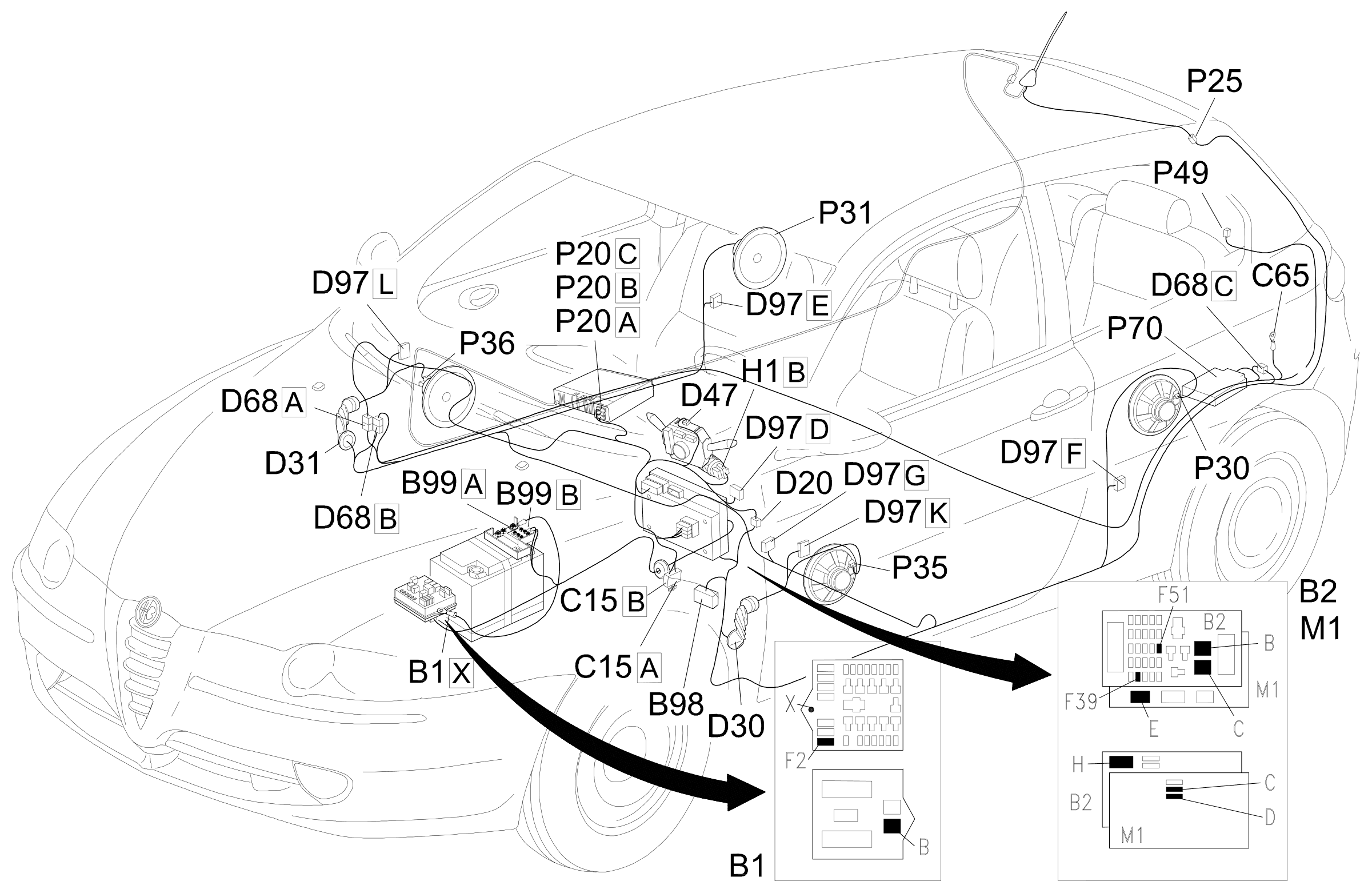
Parts & tools for this job For 2000 Alfa Romeo 147
- TOOLDigital multimeterSearch: automotive digital multimeter
- PARTAssorted fuse kitSearch: car fuse assortment kit
- TOOLWire crimper and connector kitSearch: wire crimper connector kit
Links open Amazon search results in a new tab. As an Amazon Associate I earn from qualifying purchases.