
E3570 Integrated radio phone
- Make
- Alfa Romeo
- Model
- 147 Factory Service Manual
- Year
- 2000–2002
- Section
- Radio accessories › E3570 Integrated radio phone
E3570 Integrated radio phone
Description
In the version with integrated radio-telephone-navigator, the telephone (GSM module and SIM-CARD reader) is integrated in the unit.
in the version without integrated radio-telephone-navigator, the car can be fitted with the preparation for the installation of a mobile phone Wiring diagram E3580 MOBILE TELEPHONE ARRANGEMENT .
This system includes:
- GSM module and SIM-CARD reader integrated in the radio-telephone-navigator;
- hands-free function via the radio speakers;
- microphone located in the front courtesy light;
- outside aerial.
An additional outside telephone receiver can be fitted, on request, which switches automatically to the hands free system.
The integrated radio-telephone-navigator is a node of the CAN network through which it exchanges information with the Body Computer and other electronic units.
The commands of the telephone function are grouped together on a conventional telephone keyboard (12 buttons), with in addition dedicated keys for emergency call.
The commands are displayed on the integrated radio-telephone-navigator display.
Some versions have a set of buttons located on the steering wheel: these, in addition to the radio controls, allow commands to be sent for the telephone function.
There is also the 'voice recognition' function: this is an internal voice recognition module which acquires the commands received from the microphone and interprets them, sending them to the telephone unit proper.
Some commands made by the user while using the telephone are repeated on the instrument panel ('HIGH' version).
The fishpole antenna is mounted at the rear of the roof: this is a two-function aerial with two cables: one is the actual radio aerial, and one is the telephone cable with dual reception band (GSM-ETACS at 900 Hz and D.C.S. at 1800 Hz).
If the navigator is also installed Wiring diagram E4090 NAVIGATOR , the aerial has three functions (radio/GSM/GPS).
For more details on the operation of the telephone Characteristic of working principle 5570 Accessories .
Description of operation
The integrated radio-telephone-navigator P20 is supplied directly (7 of connector A) by the battery via the line of fuse F39 of the unit under the dashboard B2 and maxifuse CPL of B99.
The supply to side lights on reaches pin 4 of connector A Wiring diagram E2530 INSTRUMENT LIGHTING .
Pins 1 and 3 of connector A receive the CAN line with which the display P20 is connected to the Body Computer M1 and the other nodes of the system. Pin 8 of connector A is earthed.
The aerial P25 is supplied from pin 5 of connector A. The GSM aerial is connected to the telephone function also via the appropriate coaxial cable.
Connector B of P20 is the source of the cables carrying signals to the loudspeakers used for the hands-free function Wiring diagram E3510 CAR RADIO .
Pins 10 and 11 of connector C of P20 are connected to the steering wheel controls: the connection is via the clock spring D47; the device which controls the control buttons receives a supply controlled by the ignition (INT) from the line protected by fuse F51 of the unit under the dashboard B2, while the reference earth comes from pin 12 of connector C of P20.
Pins 9 and 18 of connector D of P20 are connected to the microphone P26; pin 12 of connector D is earthed.
The external telephone receiver P27 is supplied via the line of fuse F39 of the unit under the dashboard B2, and is connected to connector D of P20, at pins 6, 7, 8, 16 and 17.
Wiring diagram
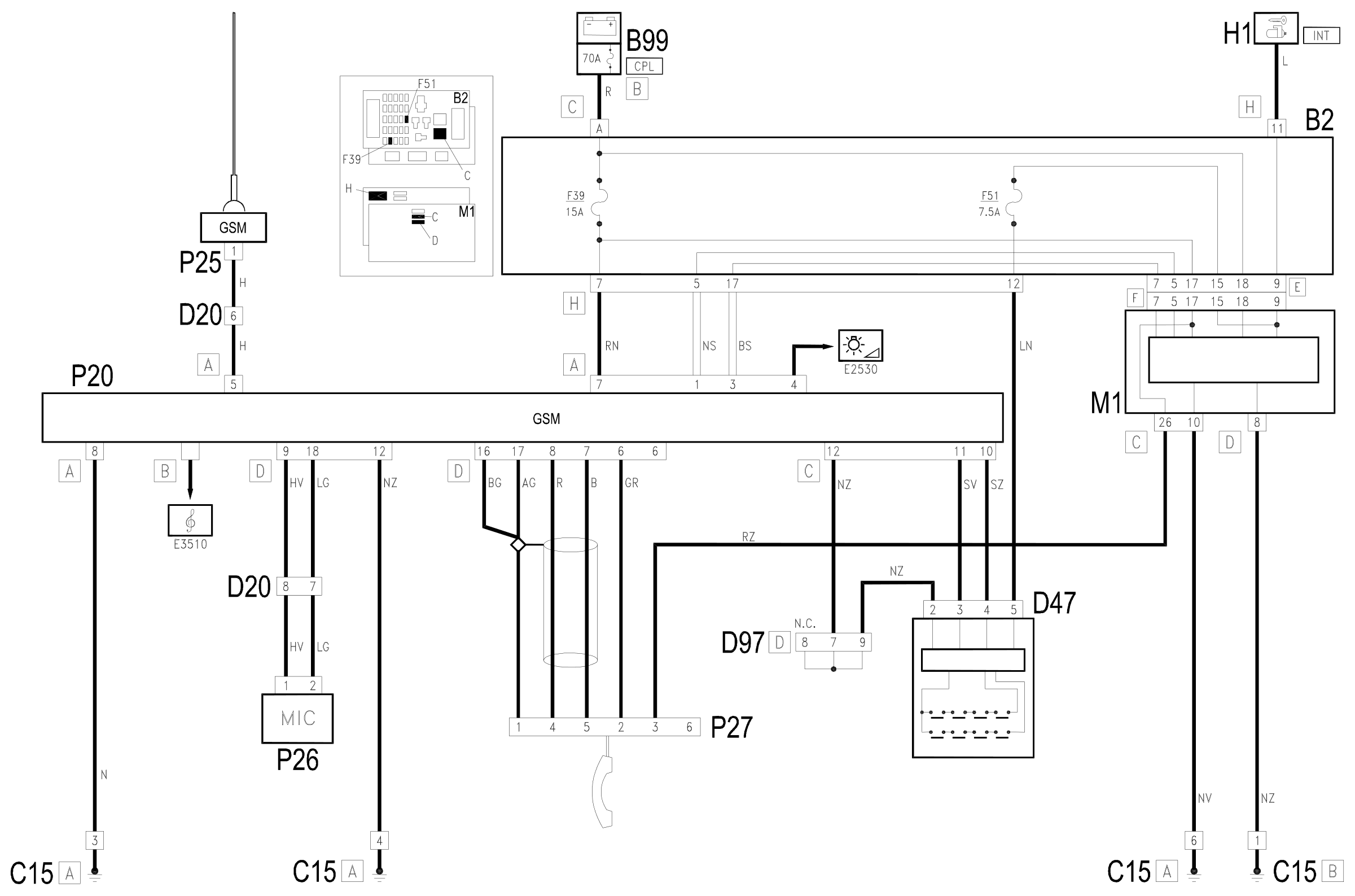
Components
| Code | Component | See |
|---|---|---|
| B02 | Junction unit under dashboard | description 5505A |
| B99 | Maxifuse box on battery | description 5530B |
| C15 | Facia earth, driver's side | |
| D20 | /Rear dashboard coupling | |
| D47 | Clock spring coupling | description 5580C |
| D97 | Short circuiting coupling | |
| H01 | Ignition switch | description 5520A |
| H10 | Controls for headlamp alignment, instrument lighting adjustment, milometer zeroing | description 5560B |
| M01 | Body computer | description 5505A |
| P20 | Car radio | |
| P25 | Aerial amplifier / feeder | |
| P26 | Microphone | |
| P27 | Telephone receiver |
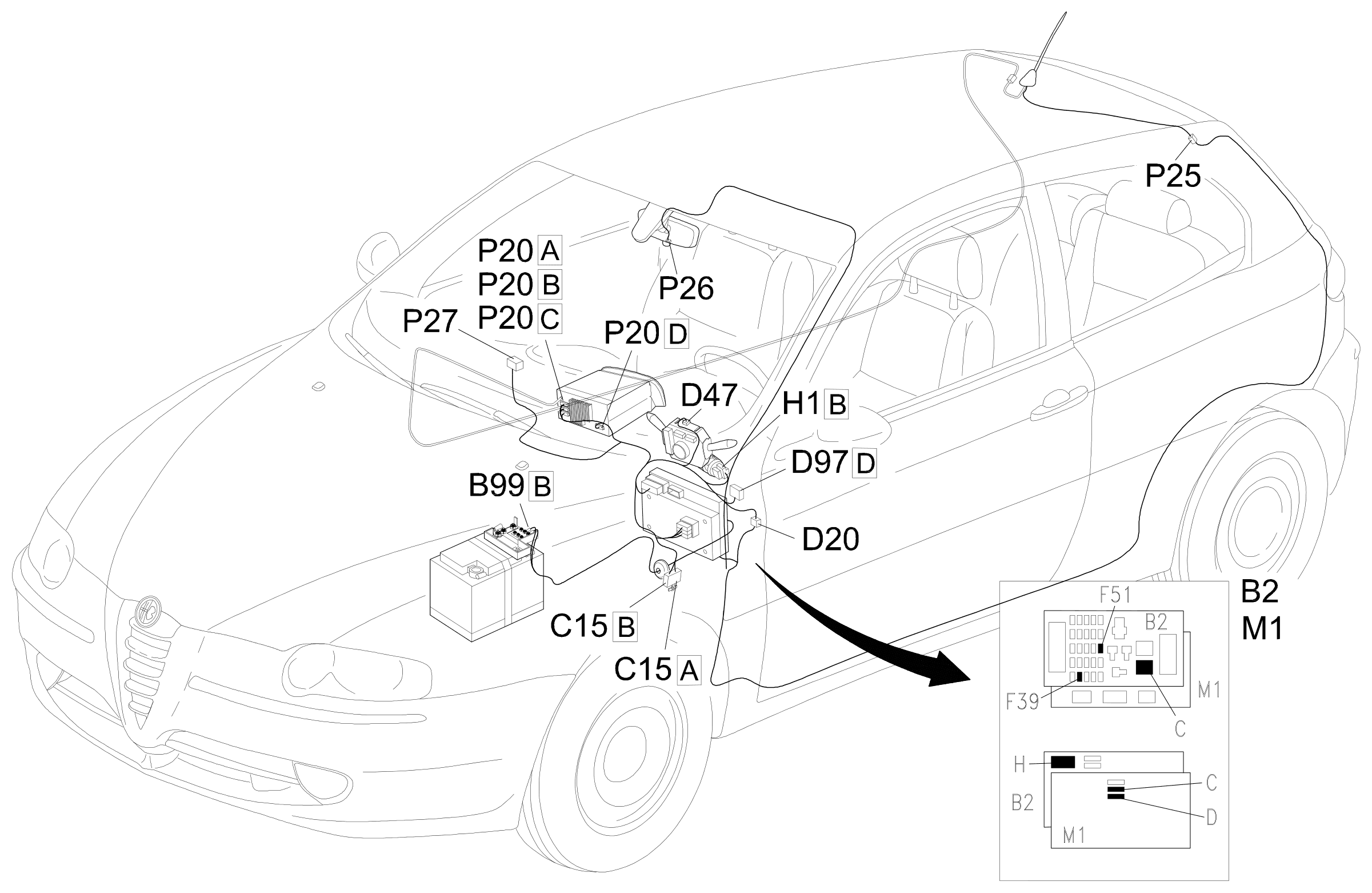
Component location
Parts & tools for this job For 2000 Alfa Romeo 147
- TOOLDigital multimeterSearch: automotive digital multimeter
- PARTAssorted fuse kitSearch: car fuse assortment kit
- TOOLWire crimper and connector kitSearch: wire crimper connector kit
Links open Amazon search results in a new tab. As an Amazon Associate I earn from qualifying purchases.